
Functional product design
Define use, geometry, materials, assembly and interfaces. Develop the CAD model and documentation needed for the next step.
MECHANICAL DESIGN / 3D CAD · PRODUCT · PROTOTYPING
Bespoke parts, mechanisms, tooling, products and machinery design. 3D CAD development, manufacturing drawings and prototypes to check a solution before taking it into production.
BESPOKE MECHANICAL DESIGN
I design parts, mechanisms, tooling, products and complete machinery. I can start with a production need, a sample or an idea that still needs to take shape: explore alternatives, develop the concept and prepare a solution that can be manufactured, assembled and used.
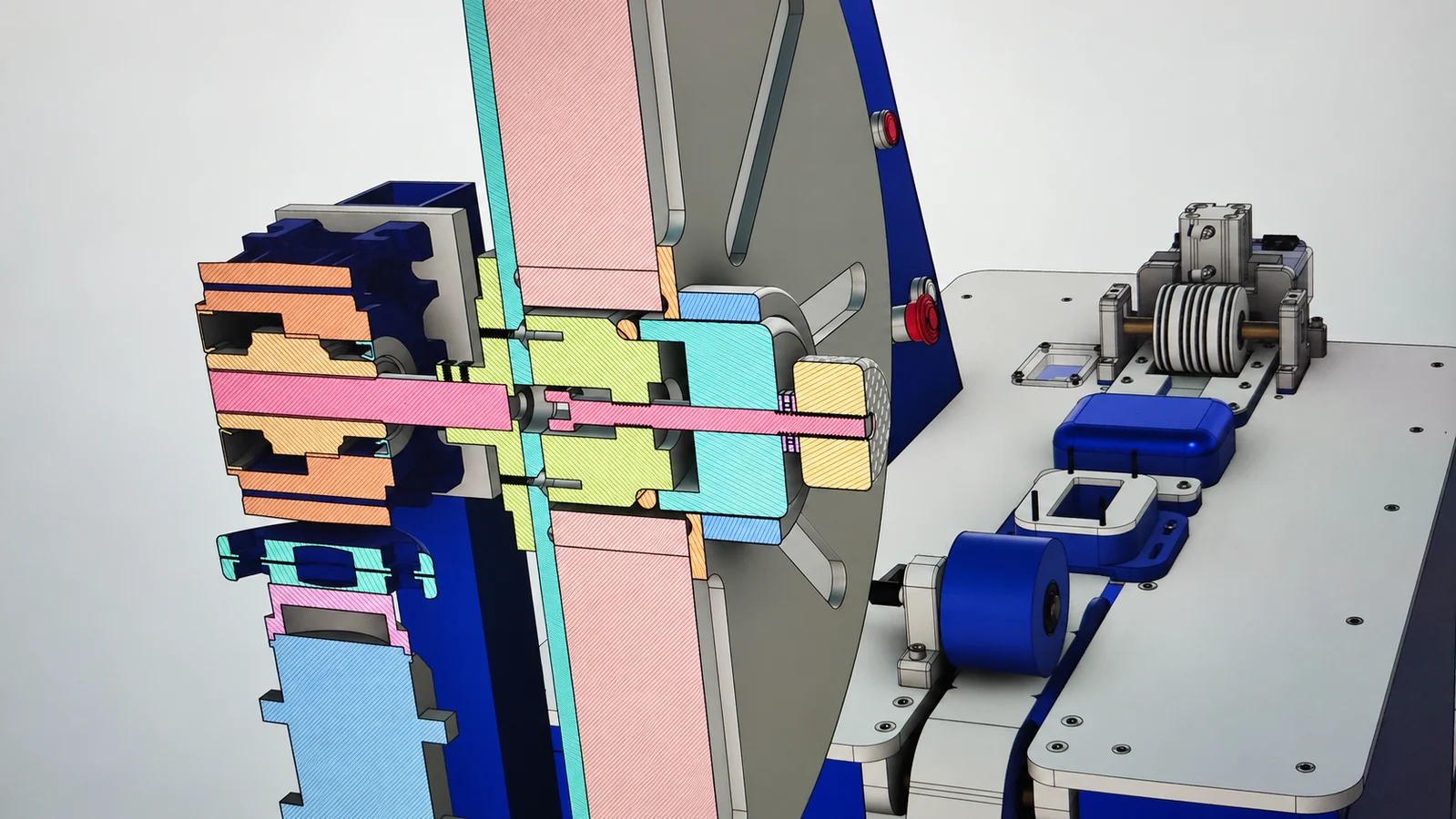
3D CAD AND MANUFACTURING DRAWINGS
I work with Autodesk Fusion, Autodesk Inventor and AutoCAD. The 3D model helps study geometries, movements, joints, assembly and space for components before manufacture.
Within the commissioned scope, I prepare 3D models, dimensioned and toleranced drawings, parts breakdowns and manufacturing or cutting files. We agree the delivery format according to what you need to manufacture, review or continue developing.
When a project combines mechanics, electrics and control, I also develop electrical schematics and documentation in EPLAN, coordinated with the machine equipment and automation.
MANUFACTURE AND MATERIALS
I combine CNC machining with conventional machining and manual workshop fabrication: marking out, cutting, drilling, turning, milling and fitting. I also have FDM and resin 3D printing, laser cutting and TIG, MIG/MAG and MMA welding equipment.
I use CAD/CAM to prepare machining on my own 3- and 4-axis equipment. Being able to design, manufacture and test in the same workshop makes adjustments and rapid iteration easier. For work beyond my equipment capacity, I work with external partners.
I select the material according to function, loads, wear, environment and manufacturing process. I work with steel, stainless steel, aluminium and bronze; engineering plastics such as POM —Delrin—, nylon, polycarbonate and acrylic; and 3D-printing materials including PETG, ABS, ASA, flexible and carbon-fibre-reinforced materials, and engineering resins. I also use wood and other materials when the application calls for them.
Models, drawings and documentation in the right format to continue your work. STEP, STL, DWG, DXF, PDF and SVG vector files, together with the following options depending on the project type.
F3D and F3Z; Inventor IPT and IAM; STEP (STP, STEP, STE); IGES (IGS, IGES, IGE); SAT; SMT and SMB; SketchUp SKP.
3MF, STL, OBJ, FBX, SPD, USDZ and LMV/SVF.
PDF, DWG, DXF and CSV; F2T templates, Fusion CAM CAM360 files and electronics-specific FSCH, FBRD and FLBR files, according to the source document.
DWG and DXF, in an agreed version; DGN V7/V8, ACIS/SAT, IGES (IGS, IGES), STL, DWT templates and DWS standards.
PDF, DWF and DWFx, including 3D views where applicable; BMP, WMF, EPS and DXX attribute extraction. PLT/PostScript plots and PNG, JPEG, TIFF, TGA, PCX and CALS raster outputs according to the output configuration.
Schematics in PDF with navigation, DWG/DXF drawings and an EPLAN project backed up as ZW1. Project delivery and formats are agreed within the commissioned scope and software version.
Delivery is defined by the commissioned scope and file content: 2D or 3D geometry, mesh, drawing, table or project. An interchange format may retain different information from the original file.
Product design and prototyping
You do not need to commission a complete machine. I can develop a functional product, part or mechanism and test the concept before moving forward.
Define use, geometry, materials, assembly and interfaces. Develop the CAD model and documentation needed for the next step.
Prepare an initial version to check form, fit or function. Choose 3D printing, machining or other processes according to what needs testing.
Assess the prototype against its objectives, identify adjustments and refine the design before subsequent manufacturing.
It may be a technical concept, a CAD design with drawings, a physical prototype or a review with test findings. We specify it in the proposal; not every commission needs every phase.
A prototype allows an idea to be tested. Moving to a final product requires a separate definition of manufacturing, validation and conditions of use.
Discuss an idea or prototypeREAL MECHANISMS AND ASSEMBLIES
Two design and build examples: an automatic card turner and an adjustable support for numbering and personalisation printheads.
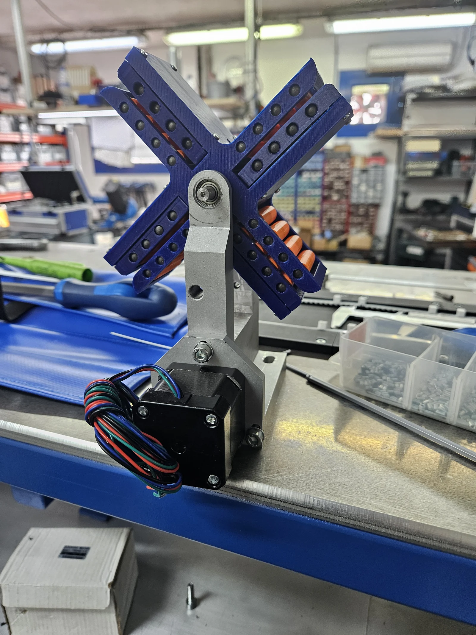
Designed and built for an automatic card inspection machine. The assembly rotates 90° at each step, organising the turning process into four stages to optimise cycle times.
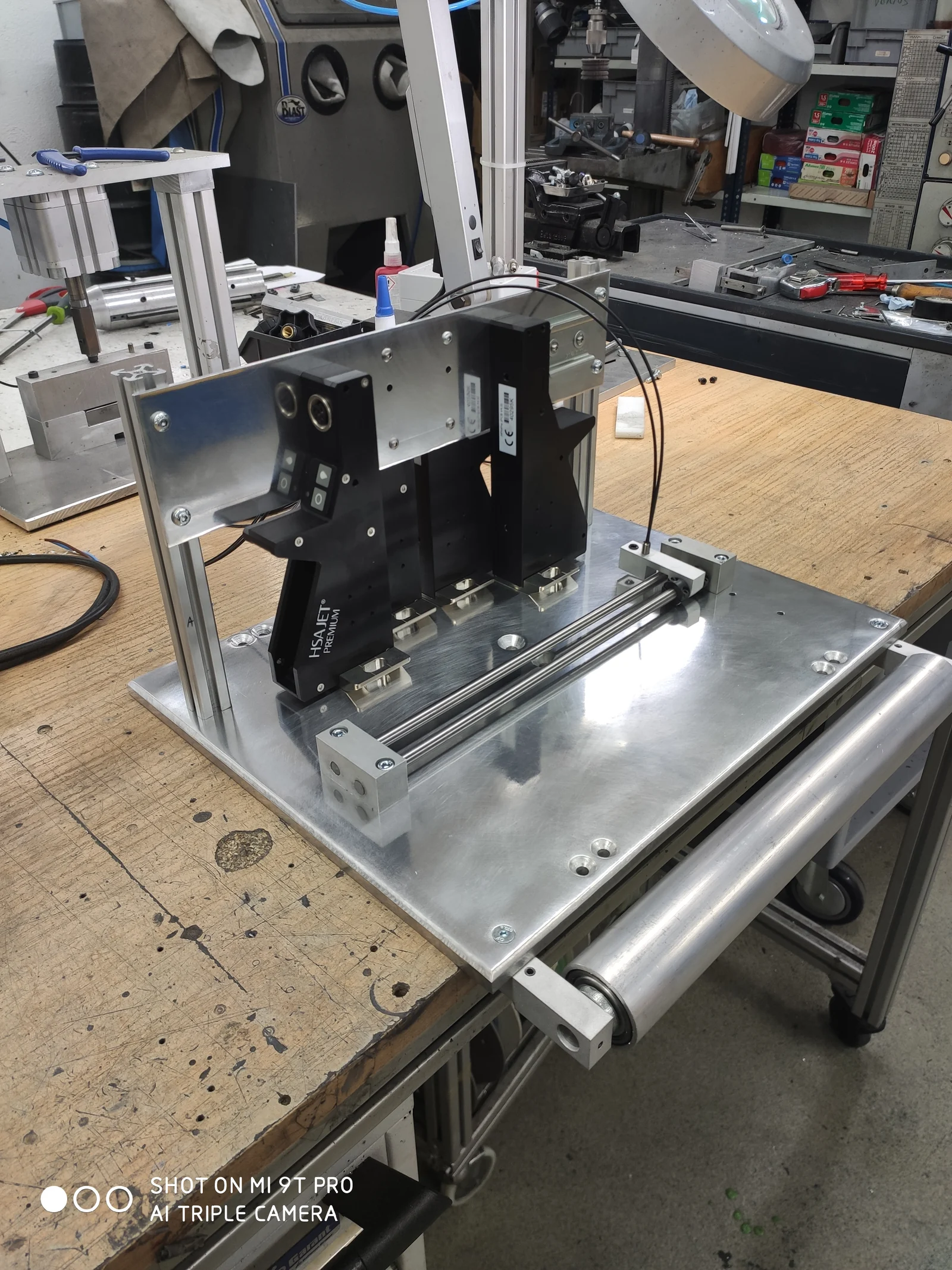
Design and construction of the aluminium support and its adjustment elements for the printheads. The assembly allows the heads to be positioned and the numbering and personalisation to be placed on the tape.
REVERSE ENGINEERING AND IMPROVEMENTS
A discontinued part or a replacement part without a drawing can be the starting point. I study its function, geometry, material and assembly to reproduce a part or propose a redesign when its operation or manufacture could be improved.
The work is defined according to equipment access, available information and the checks required. The new part must retain the interfaces and operating conditions the assembly needs.
How to identify the material of a part you need to reproduce
DIRECT CONTACT / CATALONIA AND REMOTE PROJECTS
Tell me what you need to achieve, where the solution will operate and what you have today: an idea, sketch, drawing, sample or machine in service. We can start with a study, CAD design or prototype and agree the following phases afterwards.
My usual working area is Catalonia, particularly Barcelona and the surrounding area. Design and documentation projects can be delivered remotely for clients in other countries. When a project requires travel, we agree the scope and terms beforehand.
Real evidence
From the PETG perforation tool to the RC-003 clutch and CCPB7 print adjustments: the design responds to function, lead time and operating conditions. These cases show prototypes that entered production, redesigned spares and complete machines.
Quality and inspection
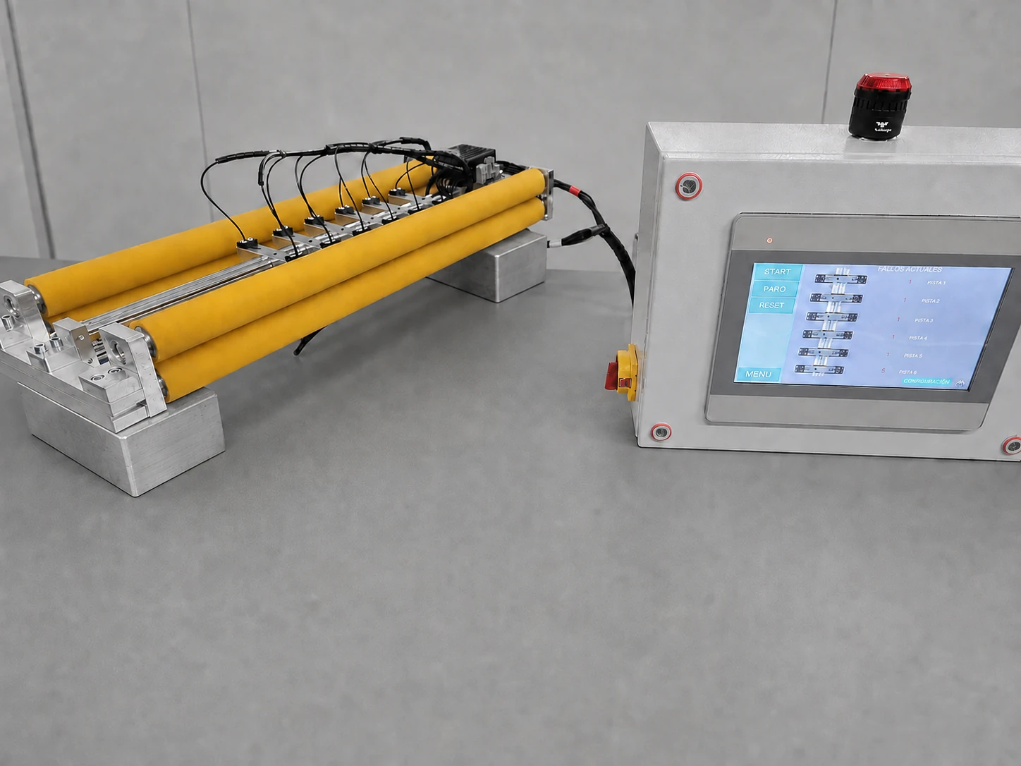
Six-track perforation inspection, integrated into an existing printing line. Mechanics, sensors and controls working as one system.
Explore the case study ↗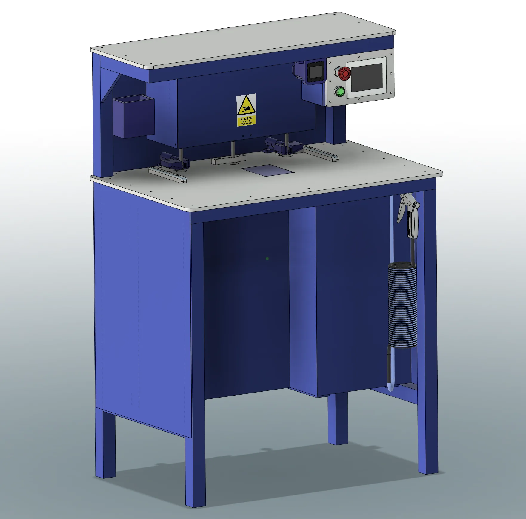
Automation and purpose-built equipment
Semi-automatic ultrasonic welding machine for multilayer stacks. From design and manufacturing to controls and improvements in service.
Explore the case study ↗
Machinery modifications
Adaptation of the cartridge holder and ribbon drive, using technical-grade ABS and an in-house clutch, to keep three machines in service.
Explore the case study ↗
Parts, spares and short production runs
A short production run of bronze backing pads, redesigned to use both faces of each replacement part.
Explore the case study ↗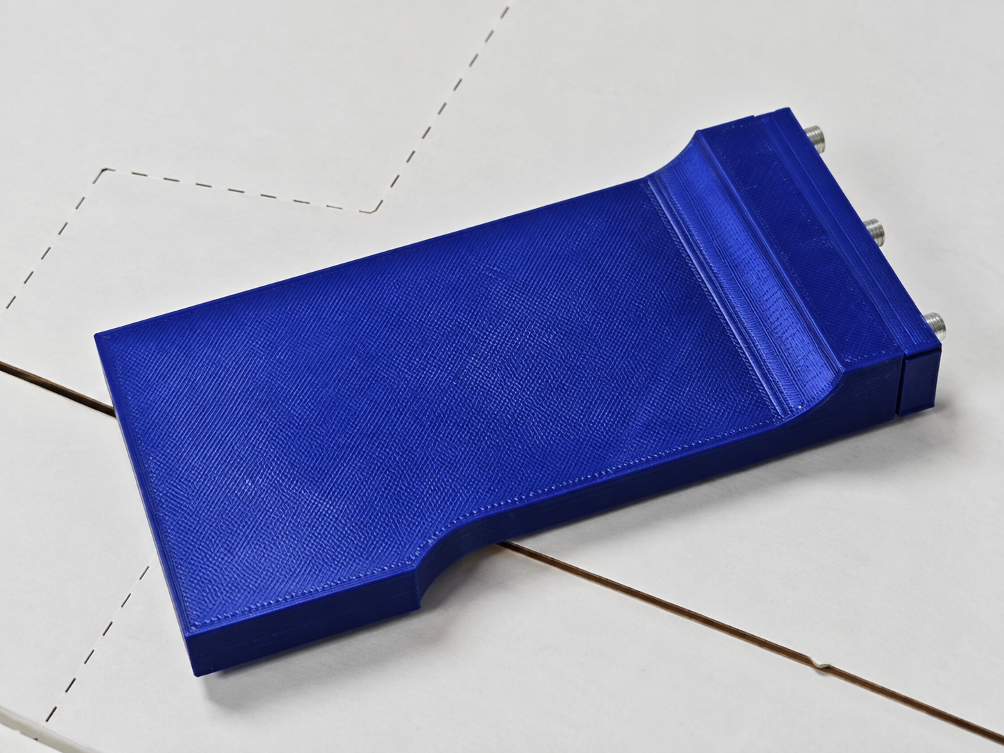
Production tooling and fixtures
Manual tool developed in under 4 hours to restore the fold perforation in a batch of boxes, with a PETG body and an alignment reference.
Explore the case study ↗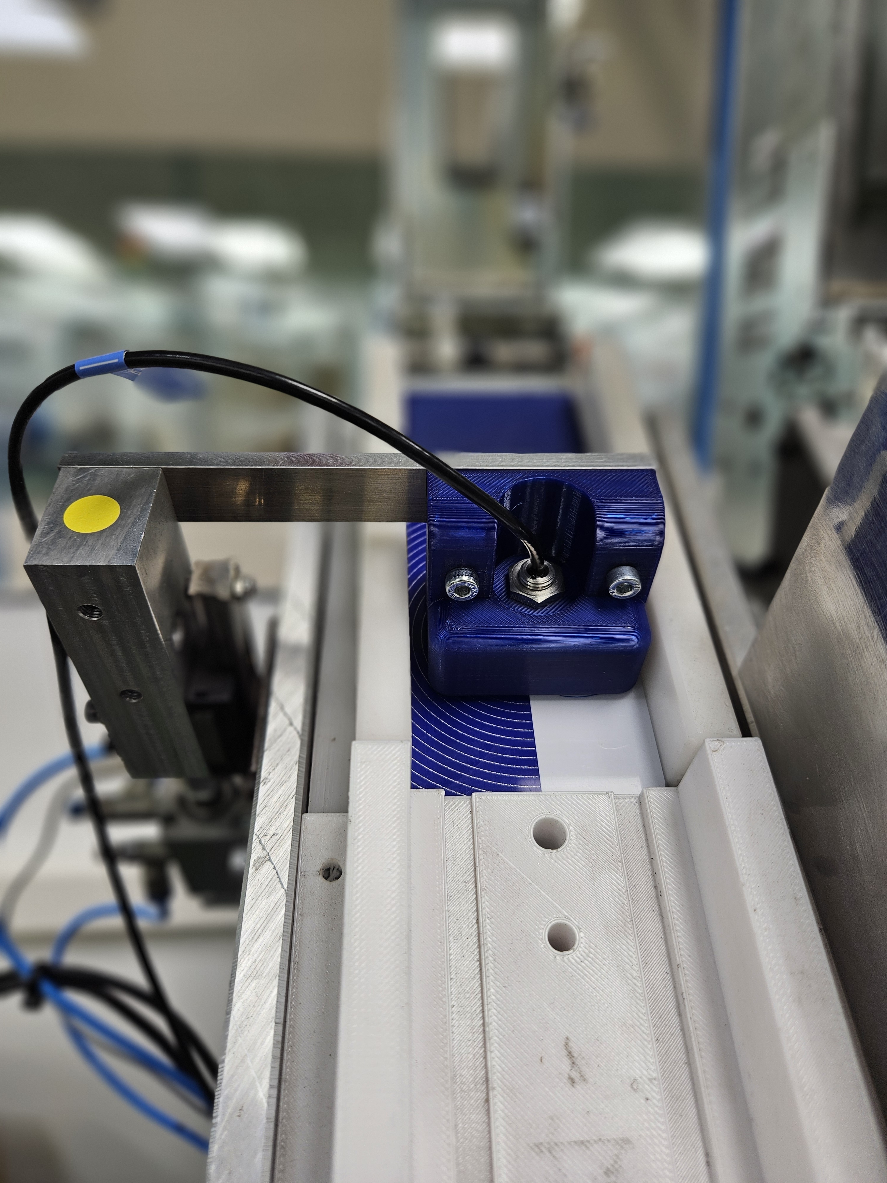
Quality and inspection
A reversible chute adaptation for card thickness inspection, combining rapid prototyping with mechanical and control integration.
Explore the case study ↗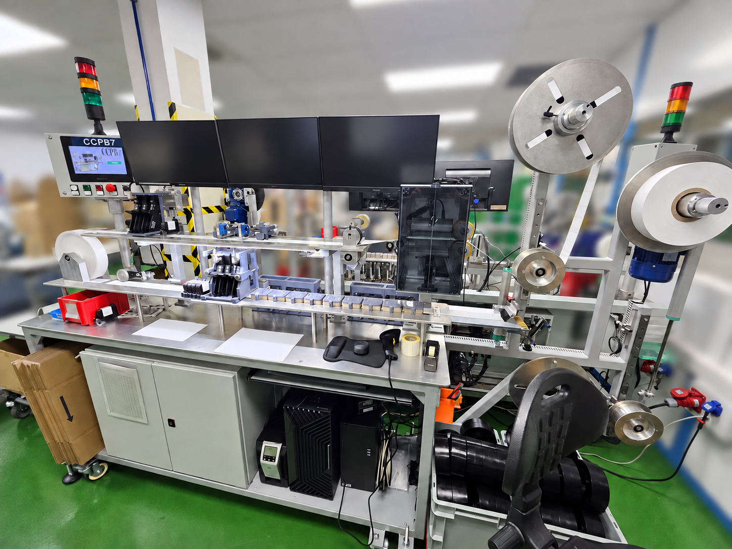
Automation and purpose-built equipment
RFID encoding, double-sided inkjet printing, vision inspection and rewinding. Six machines, with improvements extended across the series.
Explore the case study ↗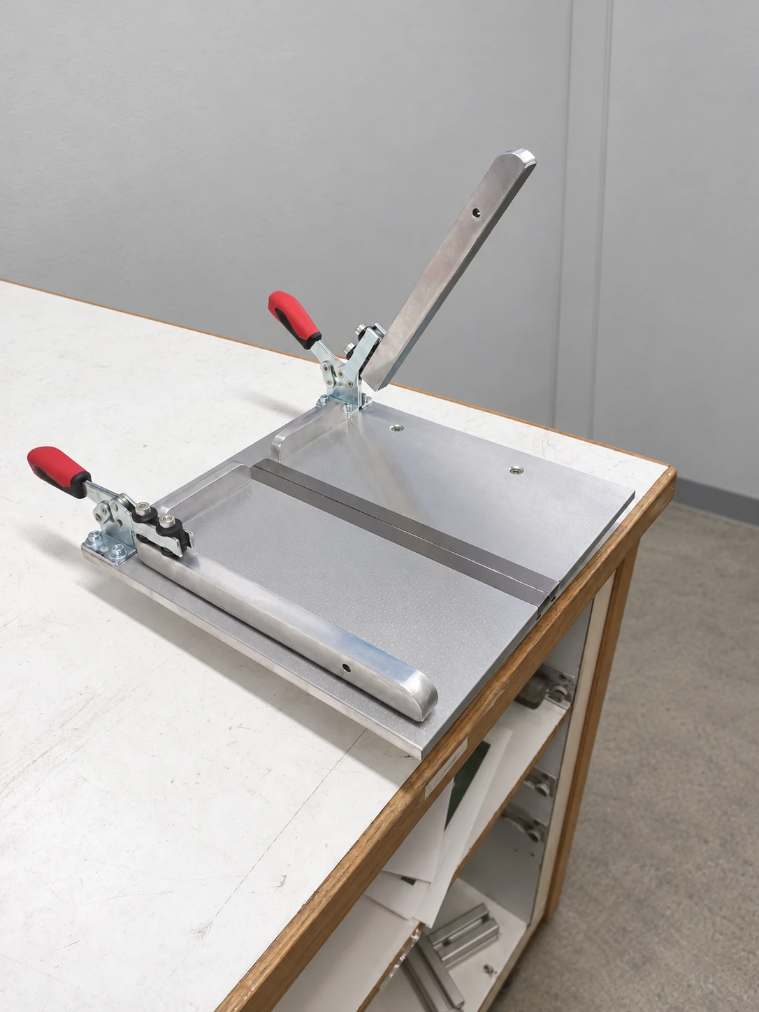
Production tooling and fixtures
A splicing table built and in use since 2021, and two variants designed for other formats and ways of working.
Explore the case study ↗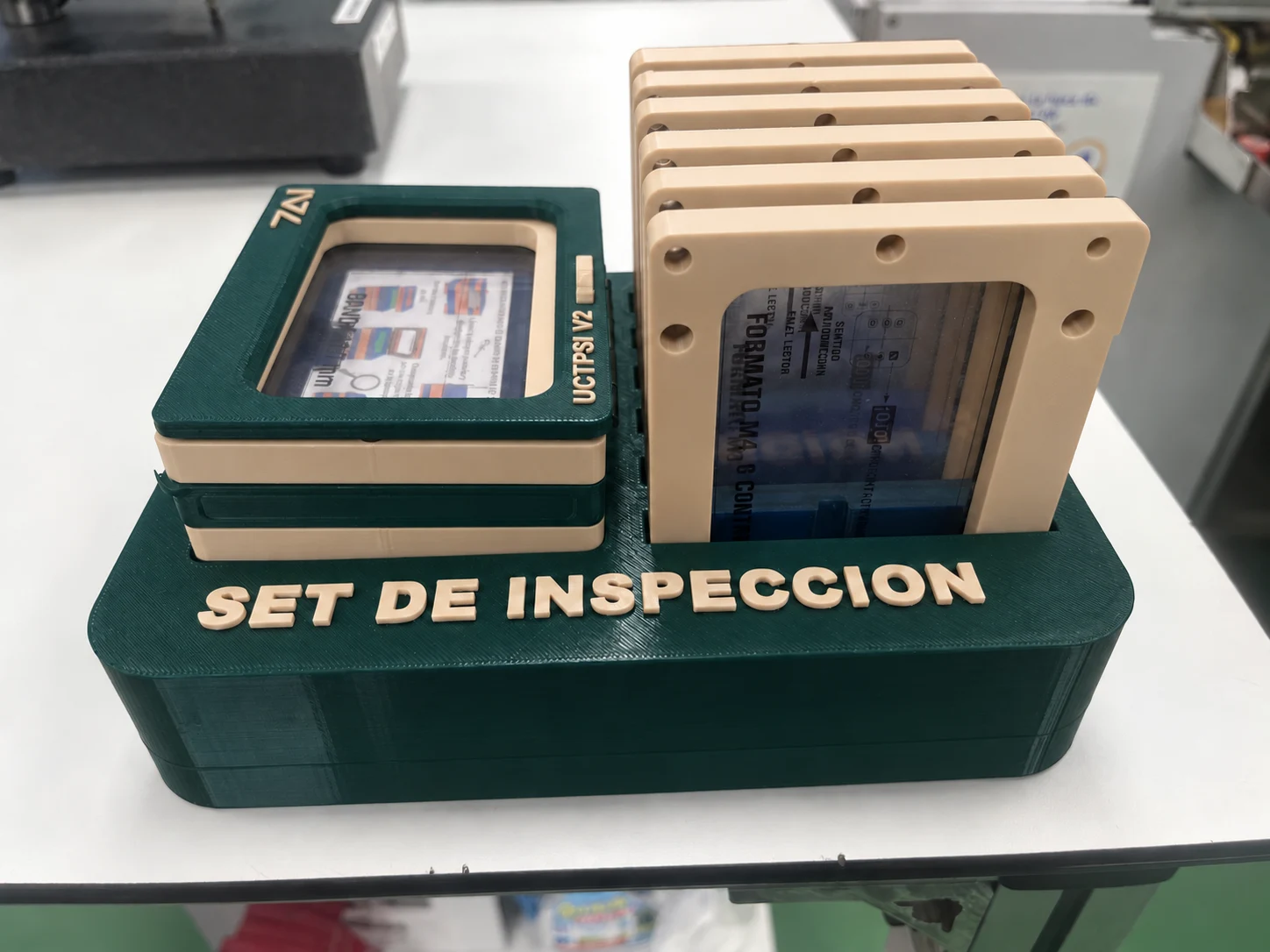
Quality, inspection and mistake-proofing
A family of quality inspection fixtures for cards and tickets: guided positioning, inspection templates and backlighting, with connection to 7AI Plataform.
Explore the case study ↗Your next step
Tell me what you want to achieve and which part, equipment or process is involved. You do not need to have the solution worked out.