In a printing and converting line, the web passes over numerous rollers. Splicing the end of one roll to the start of the next makes use of the material already threaded through the machine and simplifies the changeover.
I was asked for a simple, precise way to prepare splices. I designed and built a table that aligns and clamps both ends of the web, allows them to be cut in a single pass and helps join them with splicing tape on both sides.
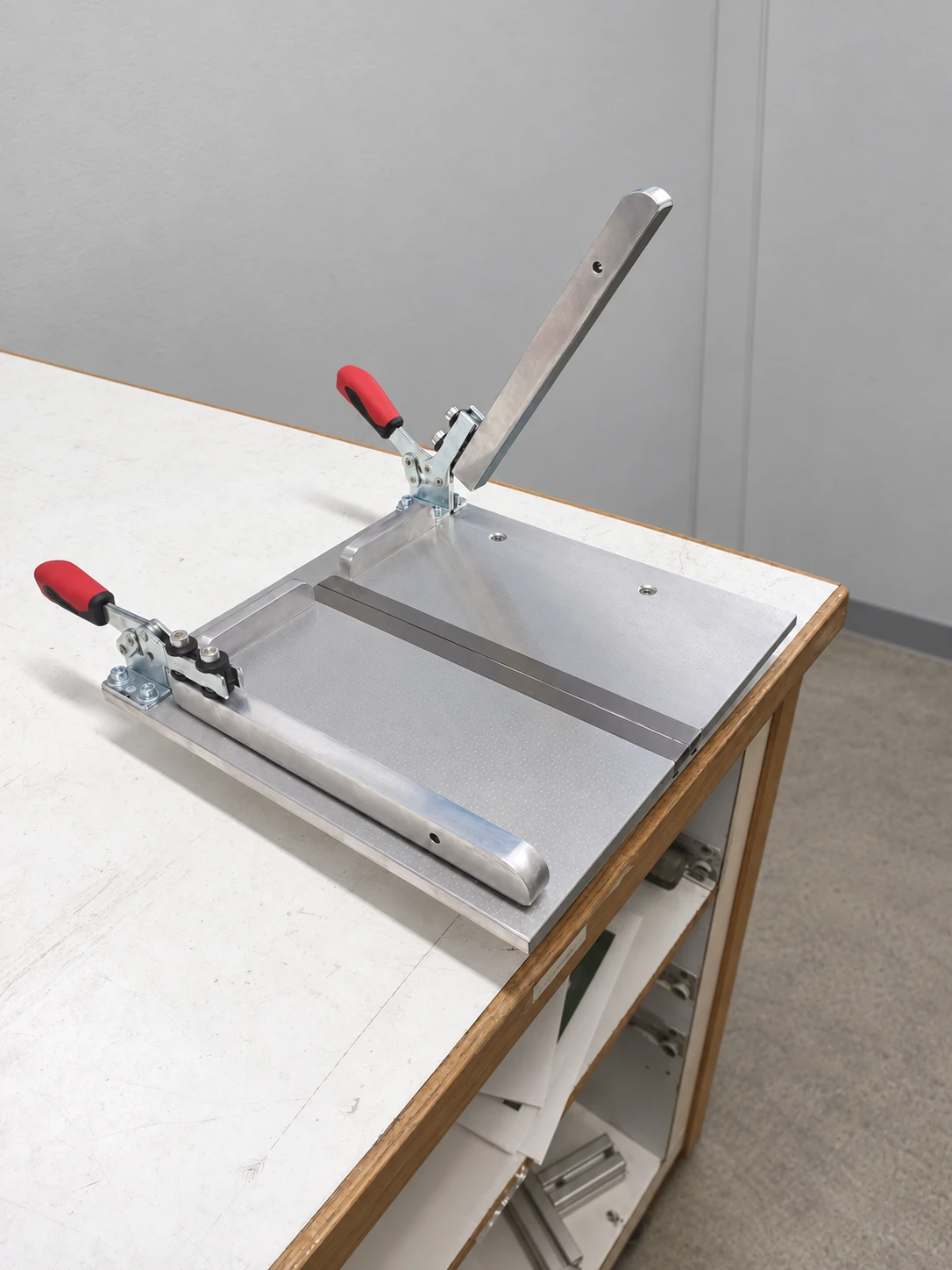
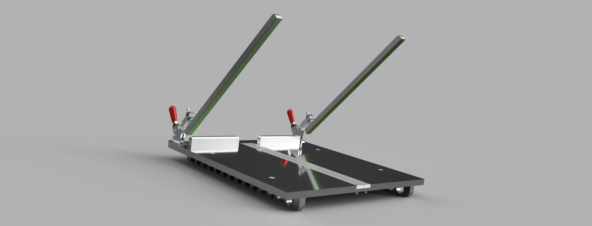
M · Assembly design with the clamping bars open.
02 / The solution
Two ends. One cut.
The side stop squares the web. The clamping bars hold the overlapping ends in place, and the blade cuts through both at once: both edges are produced in the same pass.
In all three versions — M, S and L — the clamping bars have rubber on their underside to press and hold the material without damaging it.
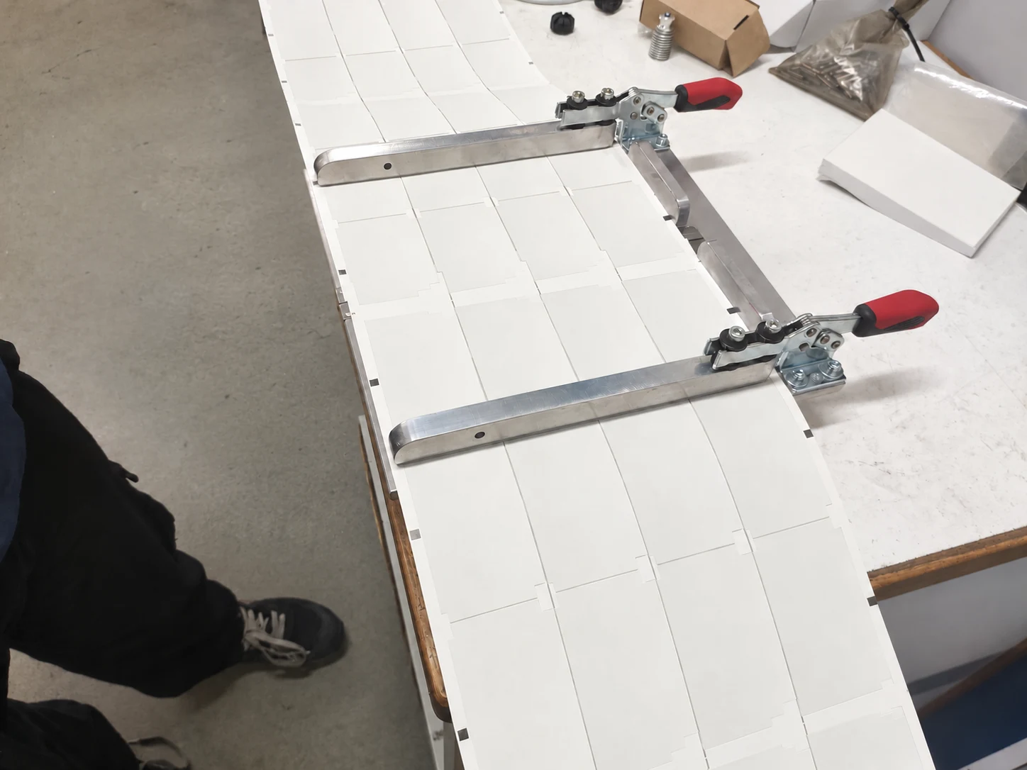
Material positioned and held by the clamping bars. Client material anonymised.
01
Align and clamp
Place the material against the stop and close the clamping bars.
02
Cut both sections
Guide the utility knife along the insert and remove the offcuts.
03
Join on both sides
Keep the material clamped, lift the edges, apply the lower splicing tape and complete the upper side.
03 / Wear
Replace the cutting surface. Keep the table.
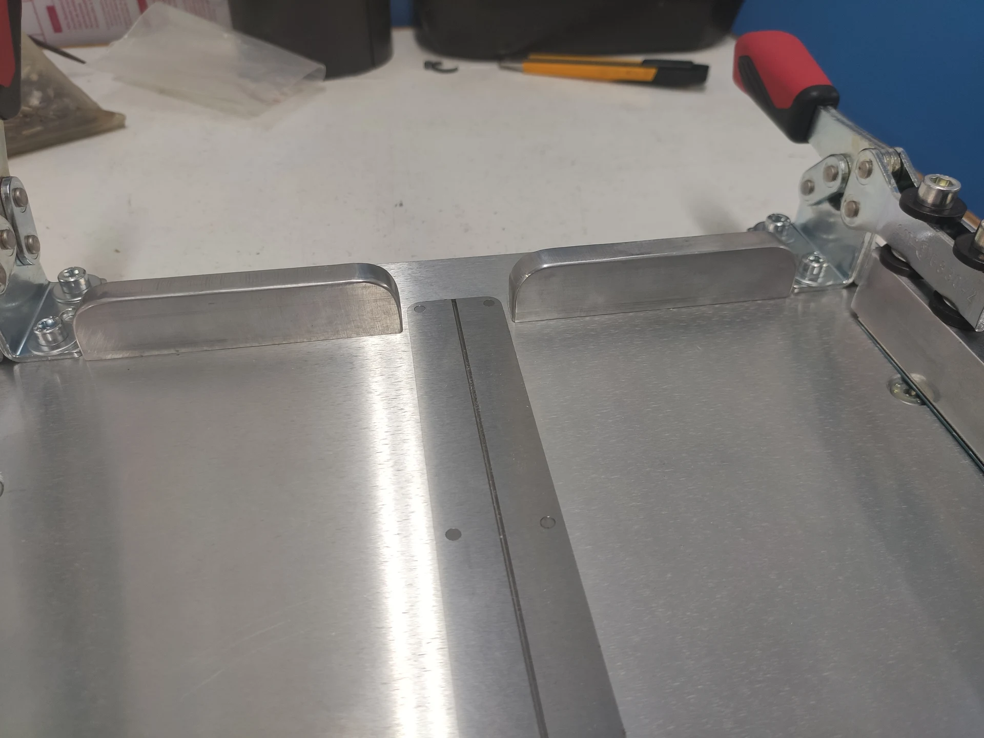
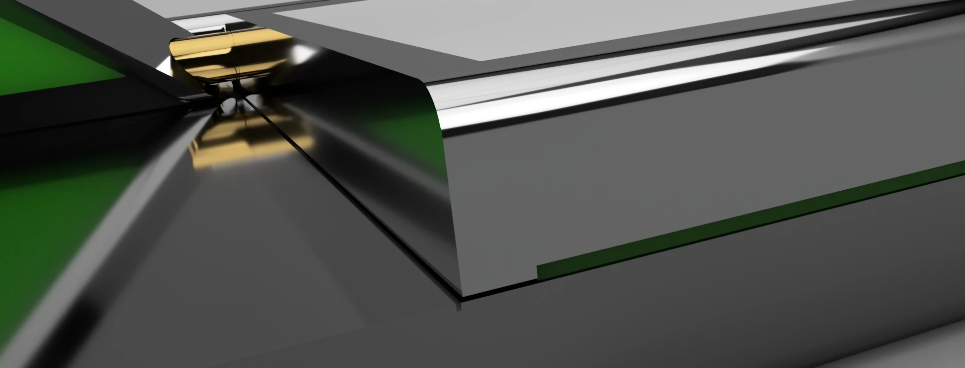
The guide uses a removable insert made from hardened material. A groove on each face allows the insert to be turned over when the first cutting surface wears, before it needs replacing.
Detail of the cutting guide and side references.
A decision for daily use
The part that wears can be renewed.
The guide performs its function separately from the main structure. Its narrow groove guides a standard utility knife during the manual operation.
From commissioning in 2021 through October 2026, the cutting guide has not needed to be turned over.
04 / From design to workshop
One unit. The complete development.
The M version was designed and built for webs less than 300 mm wide. Its 6061 aluminium structure, side references and clamping bars form an assembly intended for use on a workbench.
I carried out the design, drawings, manufacture and assembly. Only the hardening treatment of the cutting guide was outsourced.
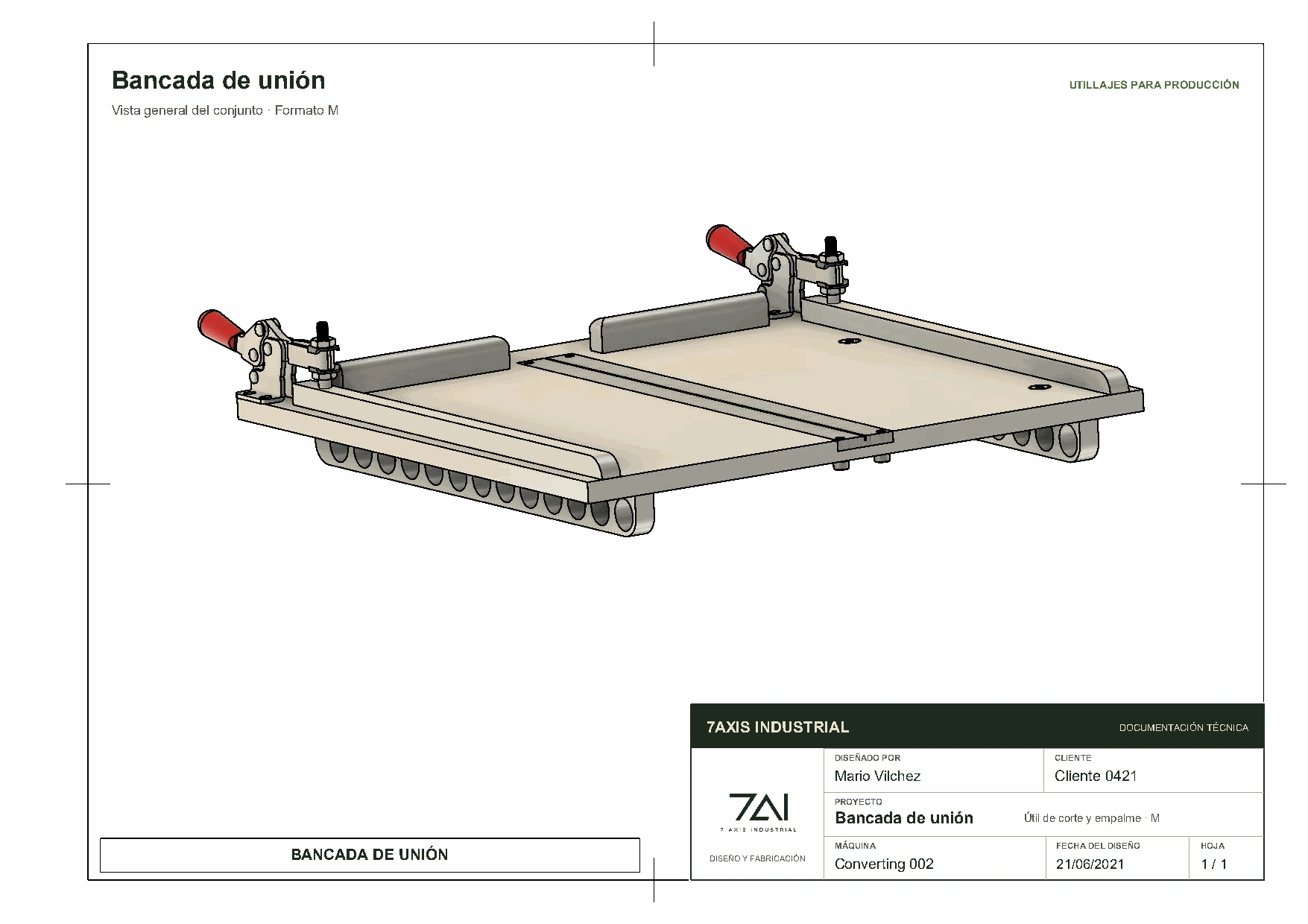
Assembly drawing · M splicing table.
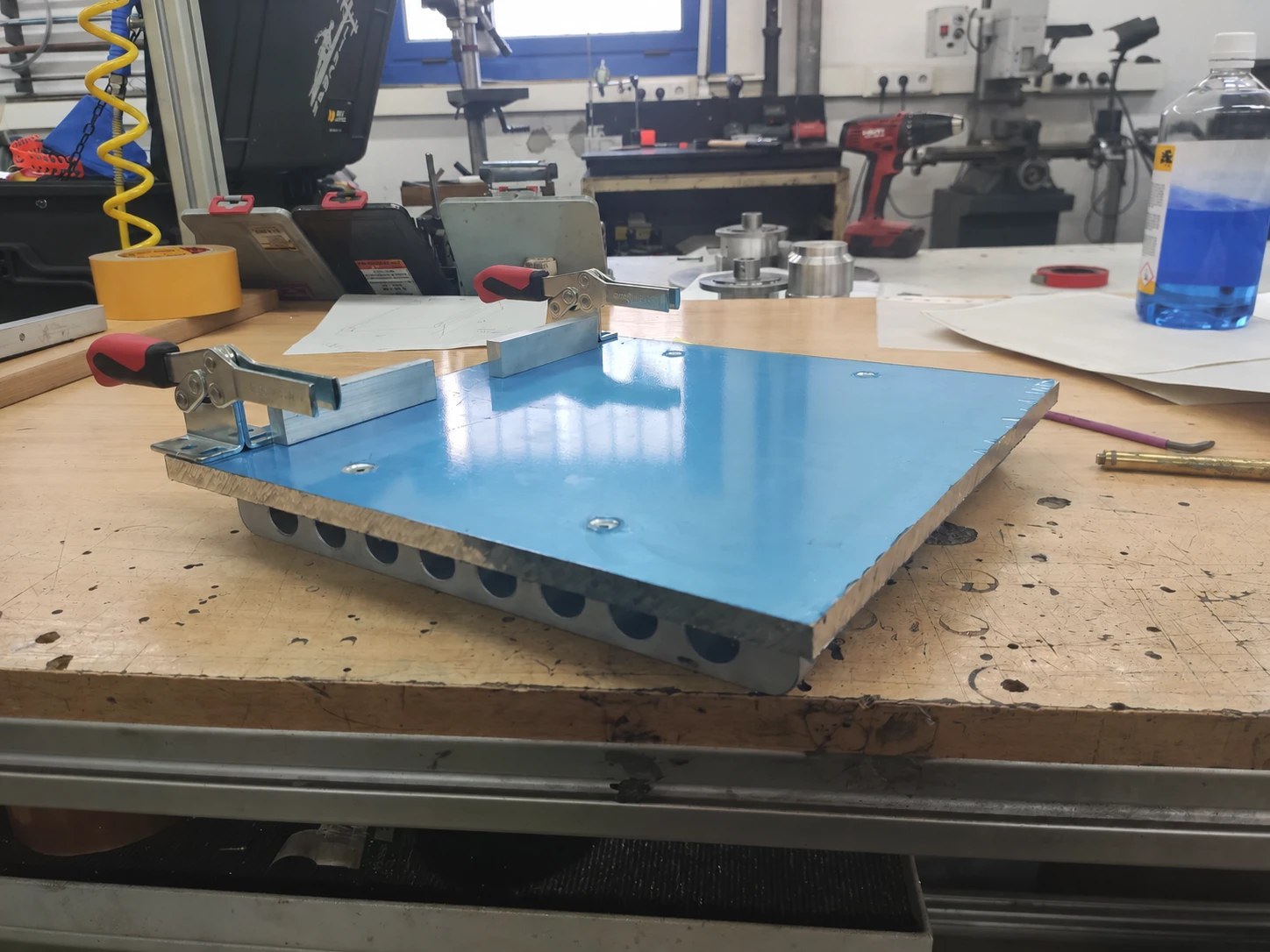
Initial layout of the base and toggle clamps, before milling.
From answering a request to developing a product
The same principle. Different ways of working.
After building the M, I continued development on my own initiative with two variants: a compact narrow-web tool and another that attaches directly to the parent roll.
M Built and in useS Compact formatL Portable format
The S and L variants remained at the design stage and were not built.
05 / S format
The same splice. In a compact format.
The S version applies the M table principle to a narrow web. It was intended for a 54 mm format, within the design range of less than 60 mm.
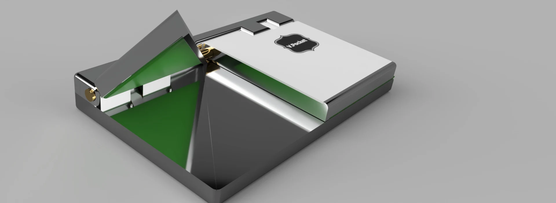
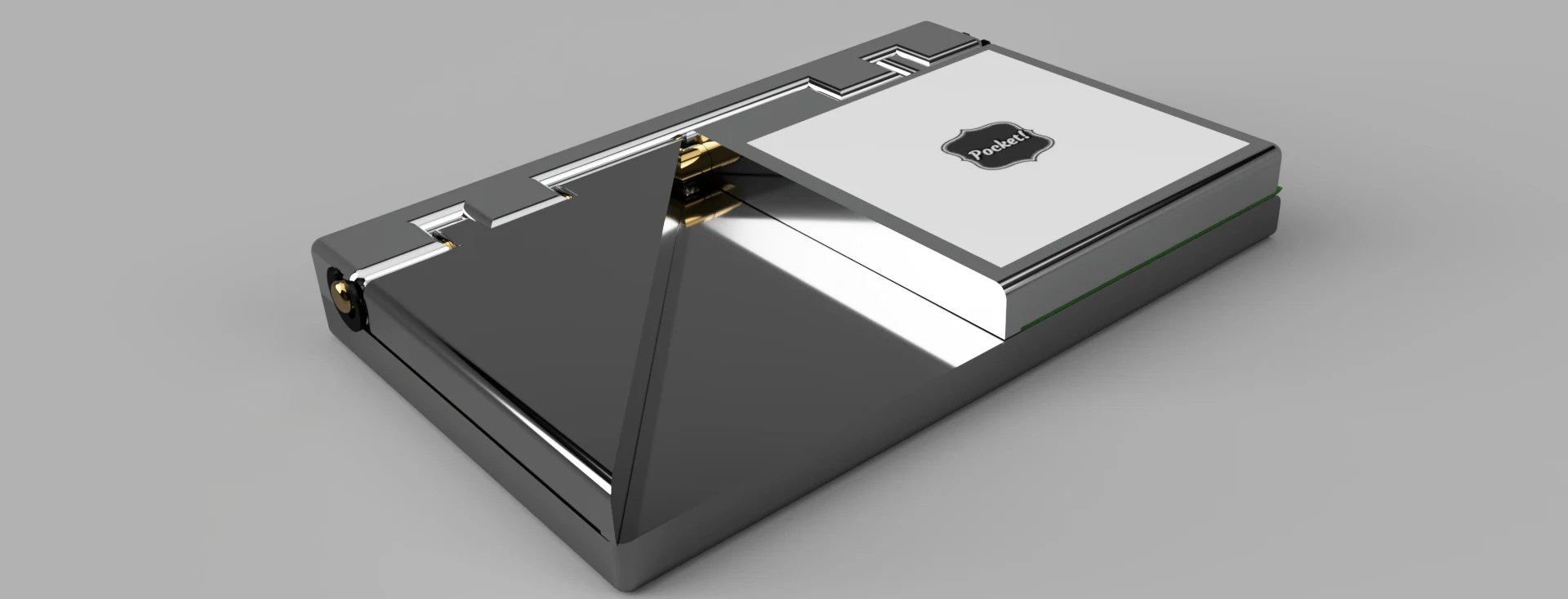
The material aligns against a side stop. Closing the pivoting pieces presses the web against the base and holds it in place for cutting. Rubber on their underside protects the material during clamping. The interchangeable insert provides two cutting paths: straight at 90° and oblique at 60°.
S · General view of the compact design and its pivoting pieces.
S · View of the closed assembly. CAD render.
Preparing the joint
01
Position both ends
Open the pivoting pieces, overlap the web ends and align them against the side reference.
02
Clamp and choose the cut
Close the pivoting pieces to press and hold the material against the base. Run the utility knife along the straight or oblique insert path to cut both ends in the same pass.
03
Complete the splice
Remove the offcuts, bring the cut edges together and join them with splicing tape on both sides.
Why an angled cut?
On a narrow web, an oblique cut produces a longer joint line than a perpendicular cut. This geometry was intended to improve splice strength when the equipment pulls the material.
S · Detail of the support area and one cutting path. Design render.
The interchangeable cutting insert retains the maintenance approach shared by the family.
06 / L format
The table attaches to the roll. Both hands stay free.
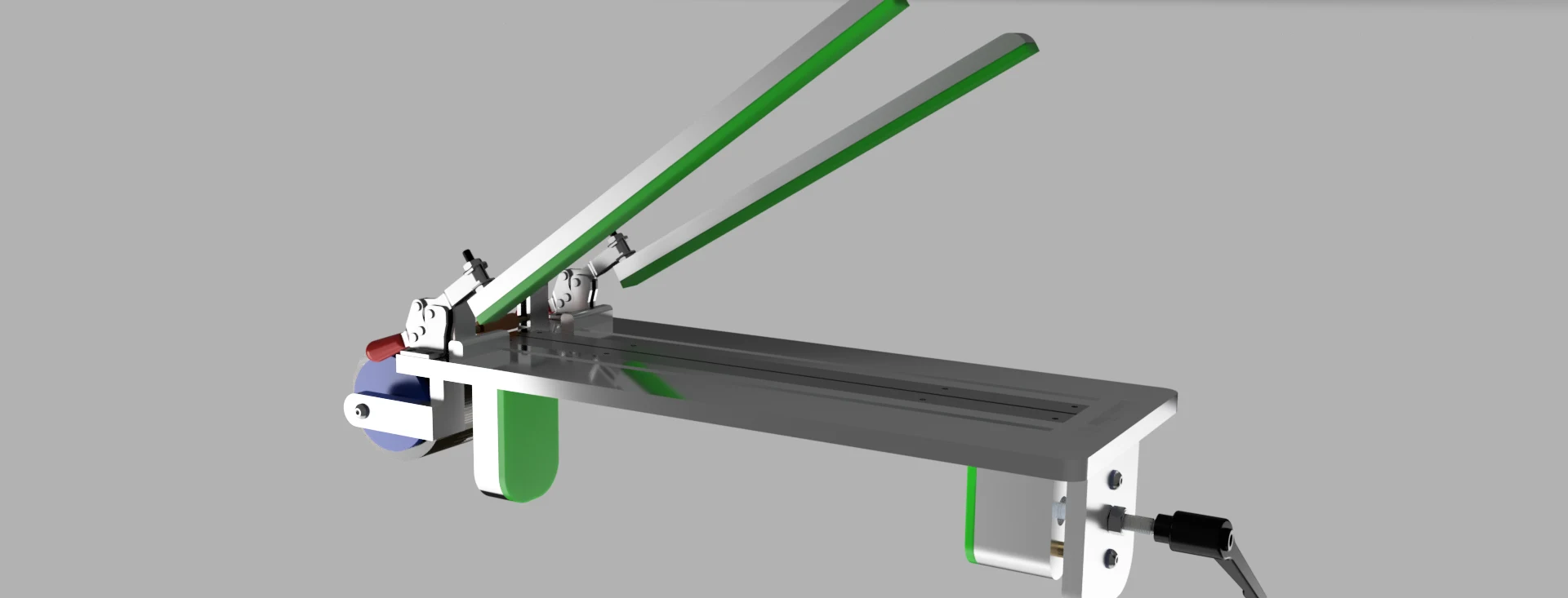
The L version was designed to prepare the splice directly on the parent roll: a large roll containing a considerable length of wound material. The aim was to provide a stable work surface beside the material, without the operator having to hold the table while cutting or applying splicing tape.
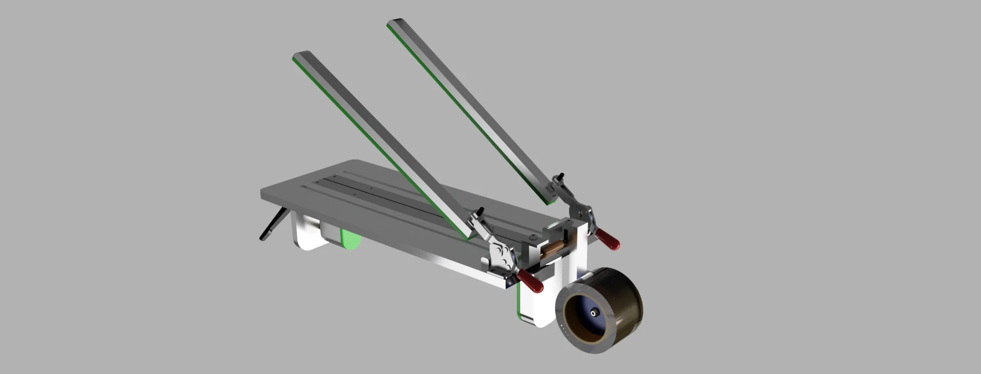
A vice adjusts to the roll width and secures the assembly. On this base, the side stop aligns both sections and the clamping bars hold them during preparation. Rubber on their underside applies pressure without damaging the web. The interchangeable cutting guide retains the maintenance approach shared by the family.
L · Render of the portable tool.
L · Assembly view with integrated splicing-tape roll and open clamping bars.
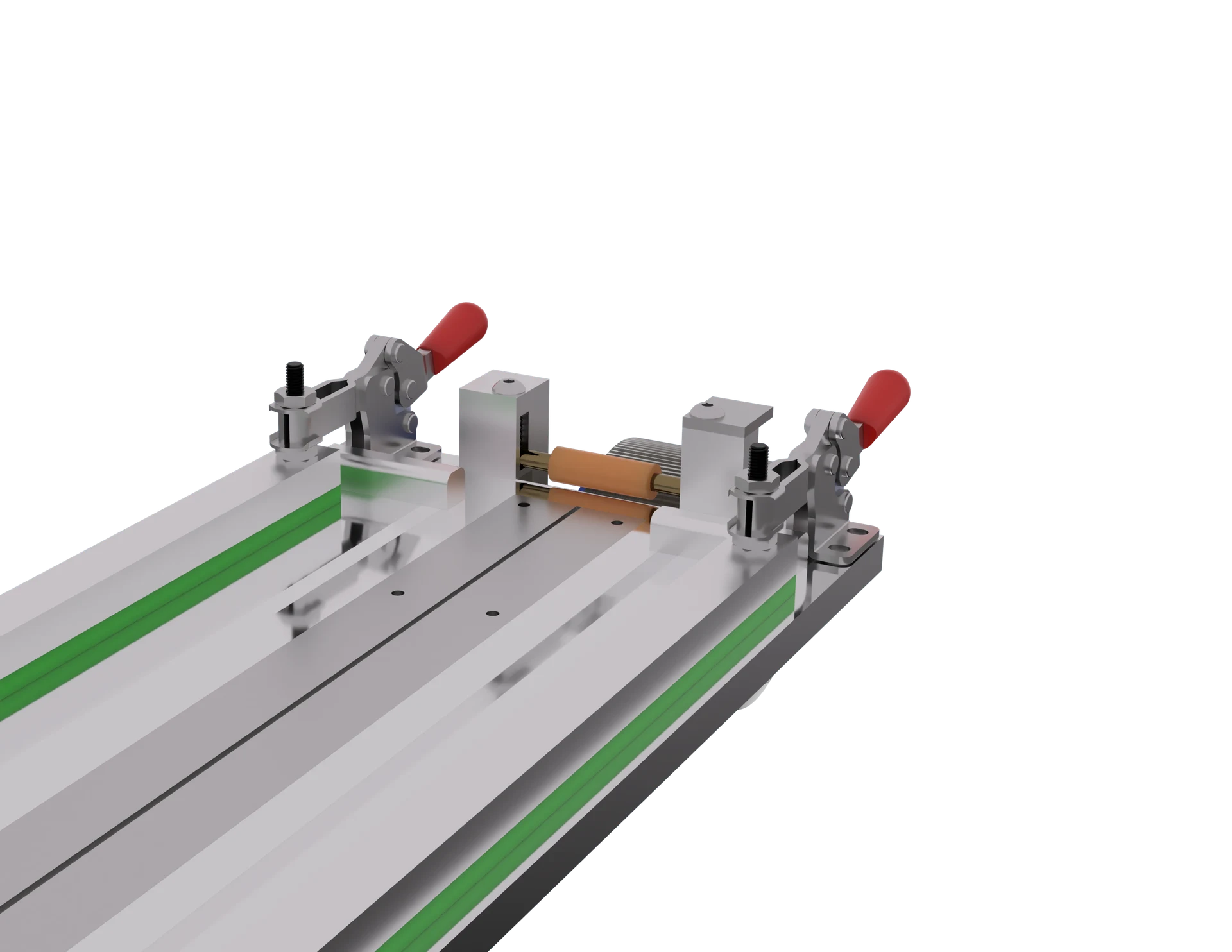
L · Detail of the proposed splicing-tape guidance system.
Hold the material while preparing the adhesive.
Once both sections have been cut and the offcuts removed, their edges are temporarily held in V-shaped recesses. The material forms an arch on each side of the joint while the clamping bars maintain the outer hold.
This leaves the tape application area clear. The recesses hold the ends up so the operator does not have to lift them with one hand while pulling splicing tape with the other.
The splicing-tape roll stays mounted on the tool. Its guides direct the tape underneath the ends with the adhesive facing upwards. The edges are then released from the recesses and placed onto the tape to secure the first side. Next, the tape is brought back over the material towards the roll to complete the joint on both sides. Finally, the surplus tape ends are trimmed and the pivoting clamps are opened to release the web.
From cutting to joining, with both hands free
01
Attach and align
Adjust the vice to the parent roll, overlap the web ends and square them against the side stop.
02
Clamp and cut
Close the clamping bars and cut both sections in one pass along the guide. Remove the offcuts.
03
Hold the ends up
Place the edges in the V-shaped recesses to form an arch. The central area stays clear for the splicing tape.
04
Prepare the underside
Pull tape from the roll mounted on the tool and extend it along the guides. Release the edges from the recesses and place them onto the adhesive.
05
Complete the upper side
Bring the splicing tape back over the material towards the roll to close the joint on both sides. Trim the surplus tape ends and open the pivoting clamps to release the web.
Bring the splicing station to the roll
The L brings the support surface, clamping and splicing-tape supply together in one portable assembly. Each element addresses part of the handling operation: the vice supports the table, the clamping bars hold the web, and the recesses retain its ends while the adhesive is prepared.
This is a manual operation assisted by tooling.
07 / Use and development
Designed in 2021. Used every day.
1unit built
2machines sharing the tool
3shifts of daily use
In October 2026, the M remains in daily use, shared between two machines across three shifts. Operators appreciate the simplicity of the operation. The cutting guide has not needed to be turned over since commissioning in 2021.
The built unit demonstrates the implemented solution. The S and L variants show how a specific requirement can become the starting point for a product family.
From the project to your requirements
Related solutions.
Articles
Related articles
A closer look at the decisions behind this solution.
When I solve a brief, I do not stop at that brief. I ask where else the same problem occurs and what the solution would look like in each case. That is how a range of splicing tools grew out of a single table.
When a roll runs out, splicing on the next avoids rethreading the entire web through the machine. But a splice only works if both edges match perfectly. The trick is not to cut well twice, but to cut just once.
Almost every tool has an area that works harder than the rest. If that area is part of the main component, when it wears out, the whole tool is worn out. Designing it separately, and making it reversible, extends its life by years.