
A foundation for growth.
Phone holder for repeatable framing and a reader base to add electronic checks. Planned developments, not yet manufactured.
BESPOKE FIXTURES / QUALITY CONTROL
A family of quality inspection fixtures for cards and tickets. Guided positioning and inspection templates tailored to the actual work of each department.
This family was developed for cards and tickets. We also design bespoke fixtures for 2D parts and 3D objects, with nests, recesses and stops shaped to position them and check the features your process requires.
On a contact card, the encoding head's pins must rest on the conductive areas of the chip module. These contacts carry the power and signals required to communicate with the card.
If milling or insertion leaves the module outside the permitted positional tolerance, the pins may lose contact or make an unstable connection. This can cause encoding errors, interrupted communication or prevent the card from working in a contact reader, even if the chip itself is undamaged.
Checking the cavity position before inserting the module helps detect this deviation in time.
ISO/IEC 7816-2 defines the dimensions and position of the contacts on ID-1 cards. The contacts used in the interface include power, ground, reset, clock and data input/output. The consequences of misalignment are explained here on the basis of that electrical function and the encoding process described for this project.
ISO/IEC 7816-2 · dimensions and position ↗
Analog Devices · how the contact interface works ↗
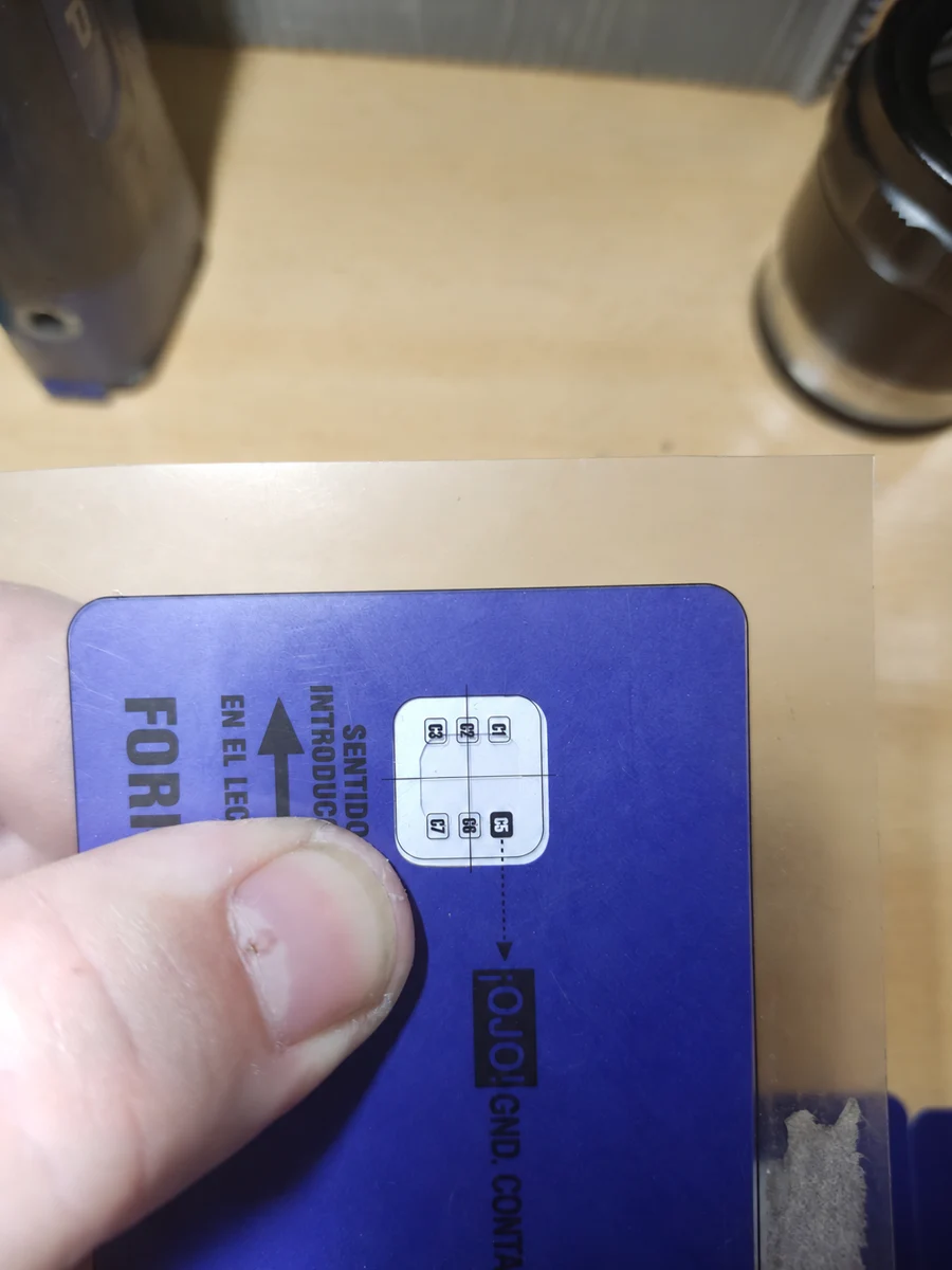
Previously, the operator slid a transparent overlay over the card until its edges aligned. Only then could the milled cavity be compared with the reference.
My first proposal was to install a machine vision system on each machine to check the chip position. The customer wanted a simpler alternative that was straightforward to use and required a modest investment. That starting point led to the first multiple fixture: a visual check guided by a template and a reference position.
The first fixtures were made from engineering ABS, with the idea of later moving to aluminium construction. Their performance in daily use allowed the plastic solution to remain: it provided the robustness and durability required for this application, with manageable manufacturing and replacement costs.
The system's positive reception led to new variants for different stations and checks. Engineering ABS evolved from the material of the first version into part of the implemented solution.
Proven in daily work. Since manufacture, the fixtures have been used across three production shifts, Monday to Friday. According to the customer's experience, no operating failures have been reported in that service.
The solution combines a nest that positions the card and a guided lid that holds the template. Its reference marks show the tolerance limits: the operator can see at a glance whether the part falls within them.
The nest and lid stops help reduce alignment errors during inspection. This poka-yoke approach establishes a repeatable reference for visual inspection and tolerance checks; the operator compares the part with the template and decides whether it conforms.
02 / ONE FAMILY, DIFFERENT NEEDS
Bespoke fixtures for each stage: checking the chip cavity, inspecting inlays with backlighting, print registration, and stripe and hologram inspection on continuous ticket stock.
Each fixture has a nest adapted to the format being inspected. If the card or strip does not fit, or has abnormal clearance, it indicates a possible dimensional deviation that should be checked before continuing. Positioning itself therefore acts as a format poka-yoke check.
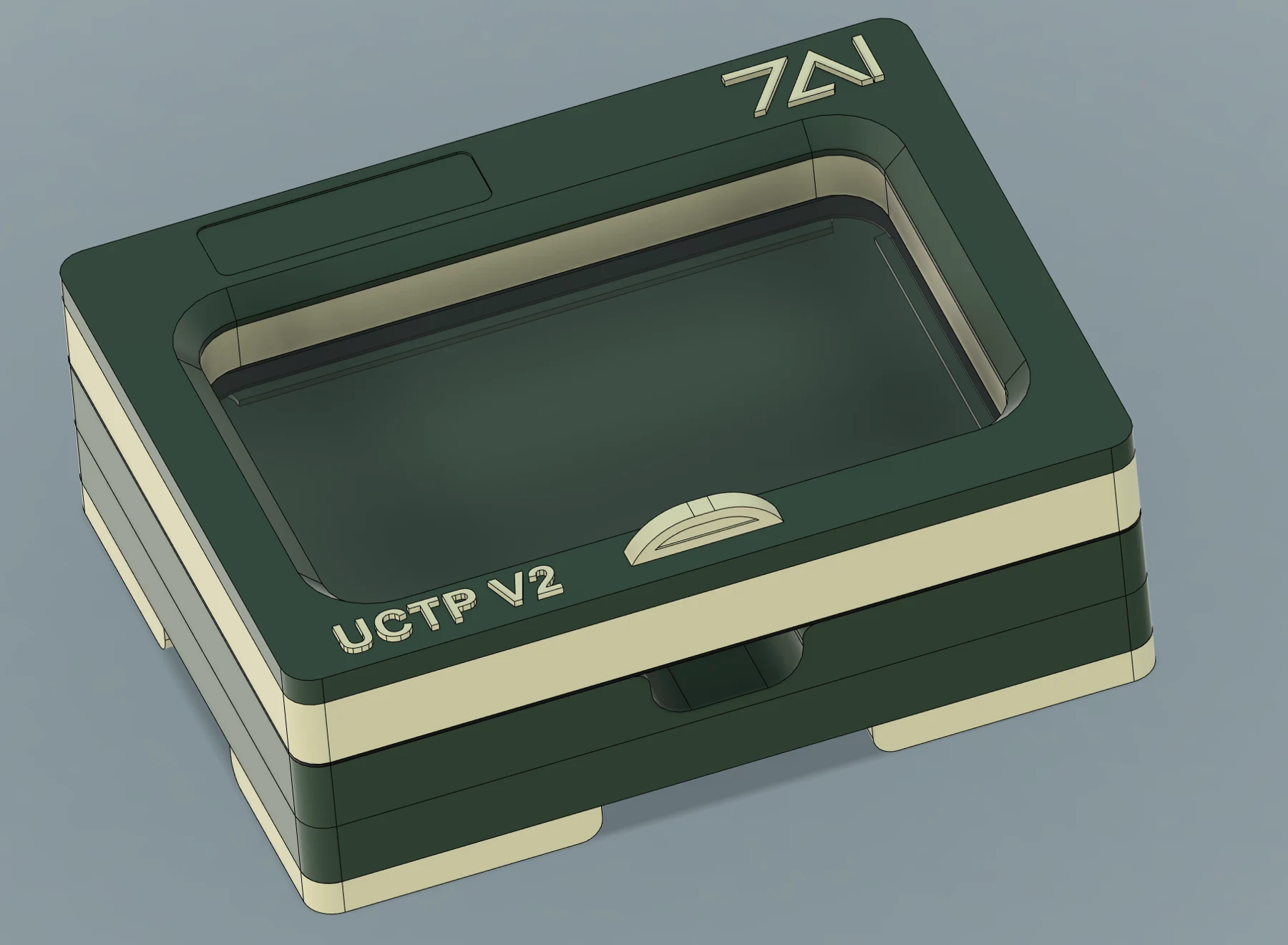
UCTP V2
01 / UCTP V2
The first multiple fixture began circulating between departments: different stations needed it for their checks. That demand led to the individual fixture, making the tool available where it was used without depending on shared equipment.
Each unit has a fixed template. At stations with small batches and frequent changeovers, operators simply choose the fixture for the relevant reference, without dismantling or reconfiguring the assembly.
UCTP V2 / FROM FIXTURE TO EVIDENCE
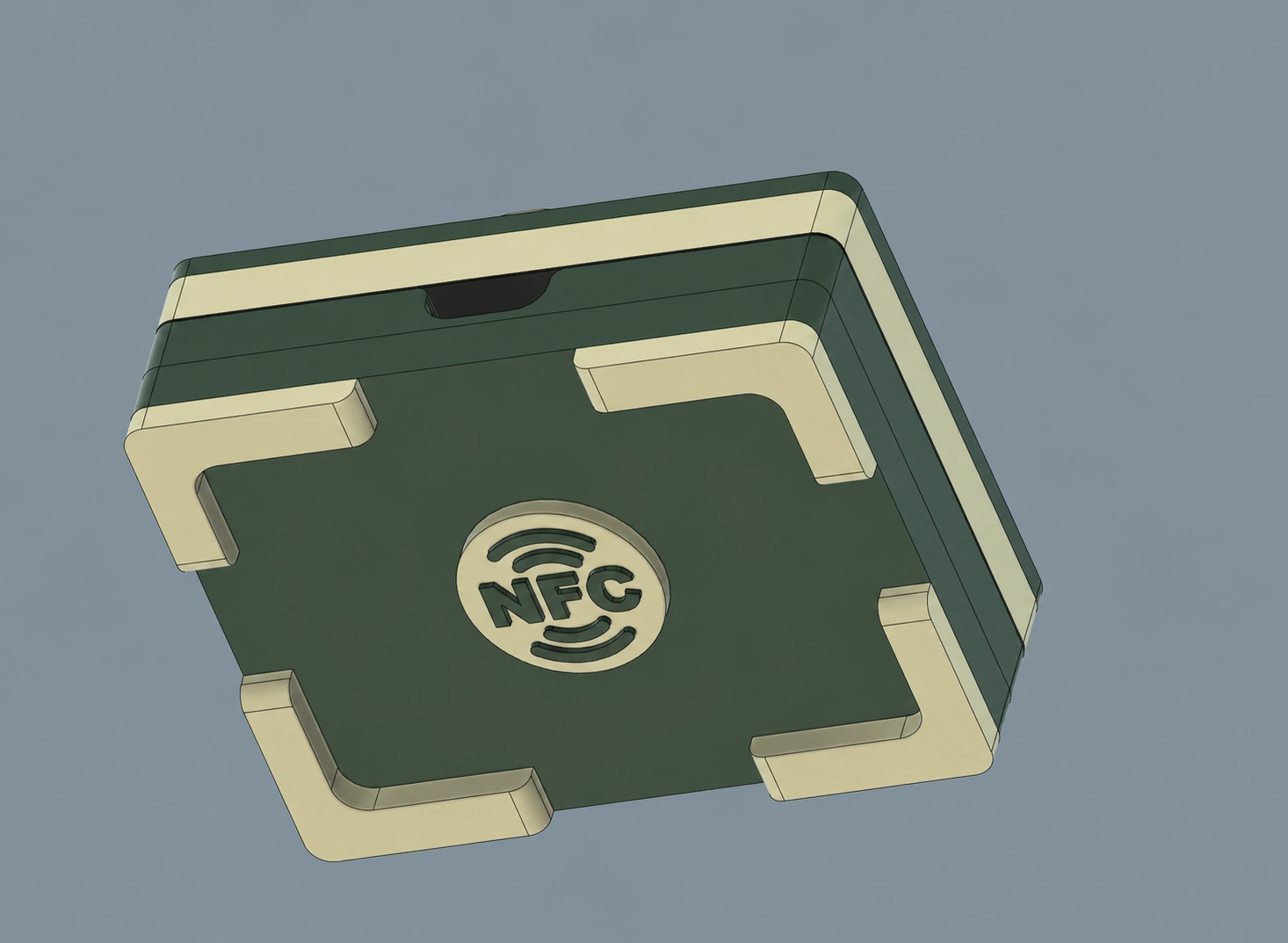
The NFC version provides access to 7AI Plataform. The photograph, result and comments accompany each inspected card.
Bring the phone close to the fixture's NFC tag and open its record.
Identify the job, photograph one or both sides and record the result.
Browse the gallery and generate reports with the inspection photographs.
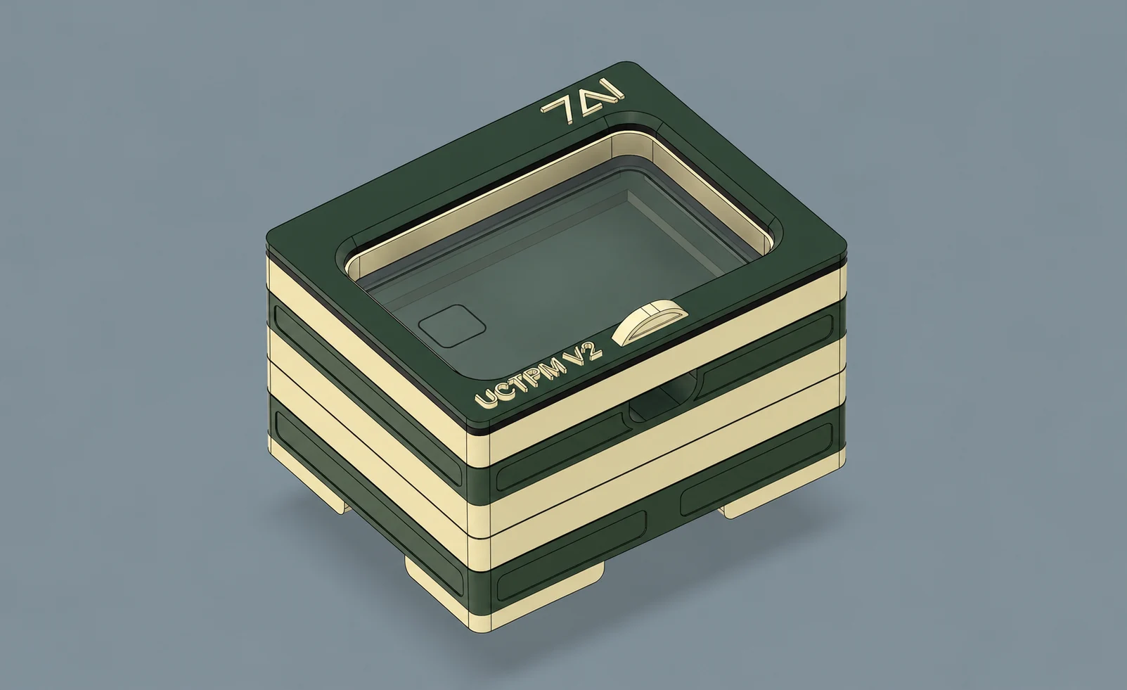
UCTPM V2
02 / UCTPM V2
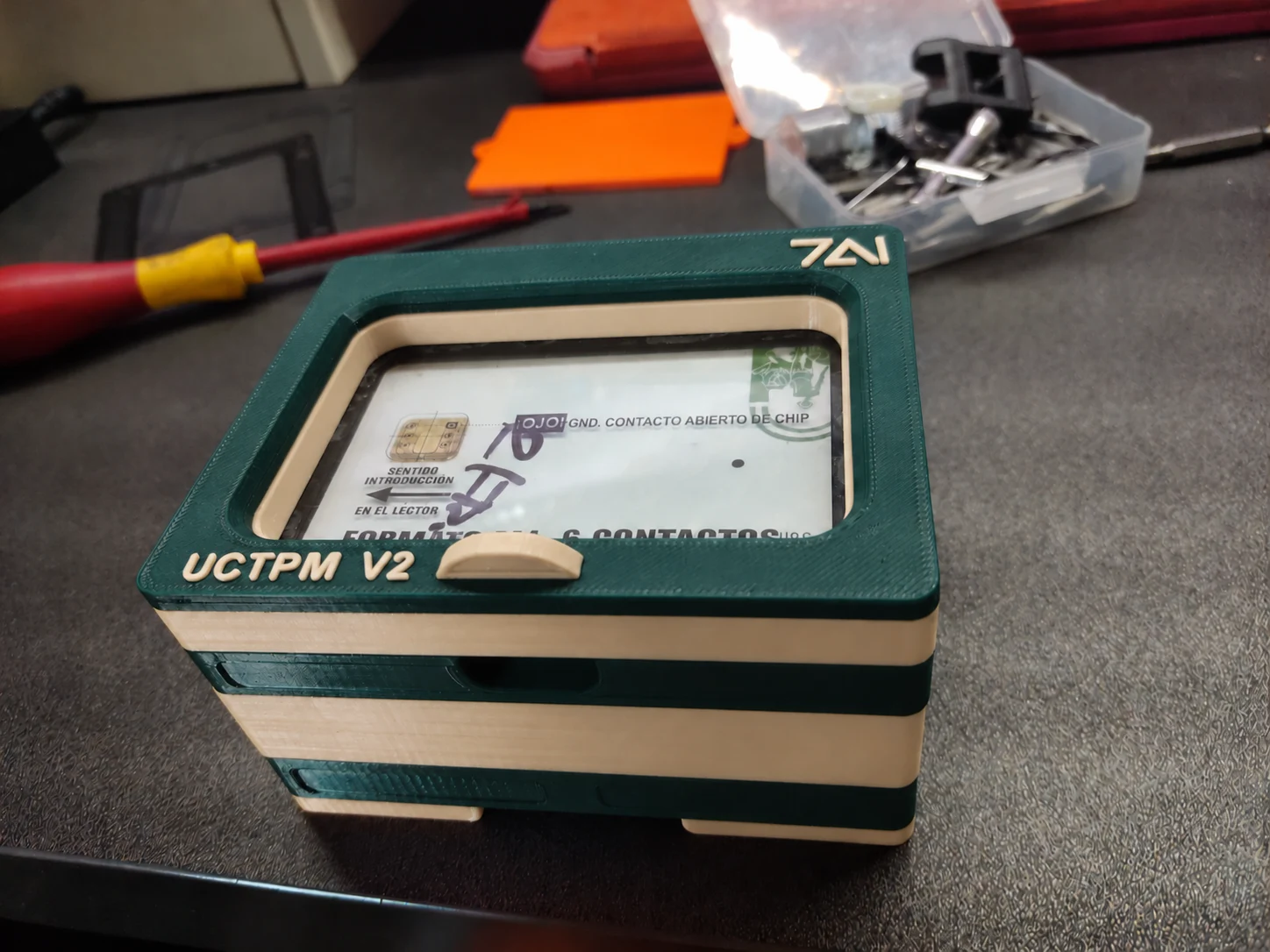
It was the first fixture in the card inspection family: a configurable assembly for checking the position of the milled chip cavity in three card references.
It began by solving a specific inspection task and was eventually also used to set up machines and check production. That experience led to the development of the other models.
01 / THE DESIGN
The initial idea involved three independent fixtures. To control costs and reduce the number of assemblies at the station, the design evolved towards a common structure with interchangeable templates.
Unused templates needed somewhere to go too. Housing all three in the assembly kept them together and available for the next changeover.
02 / AT THE WORKSTATION
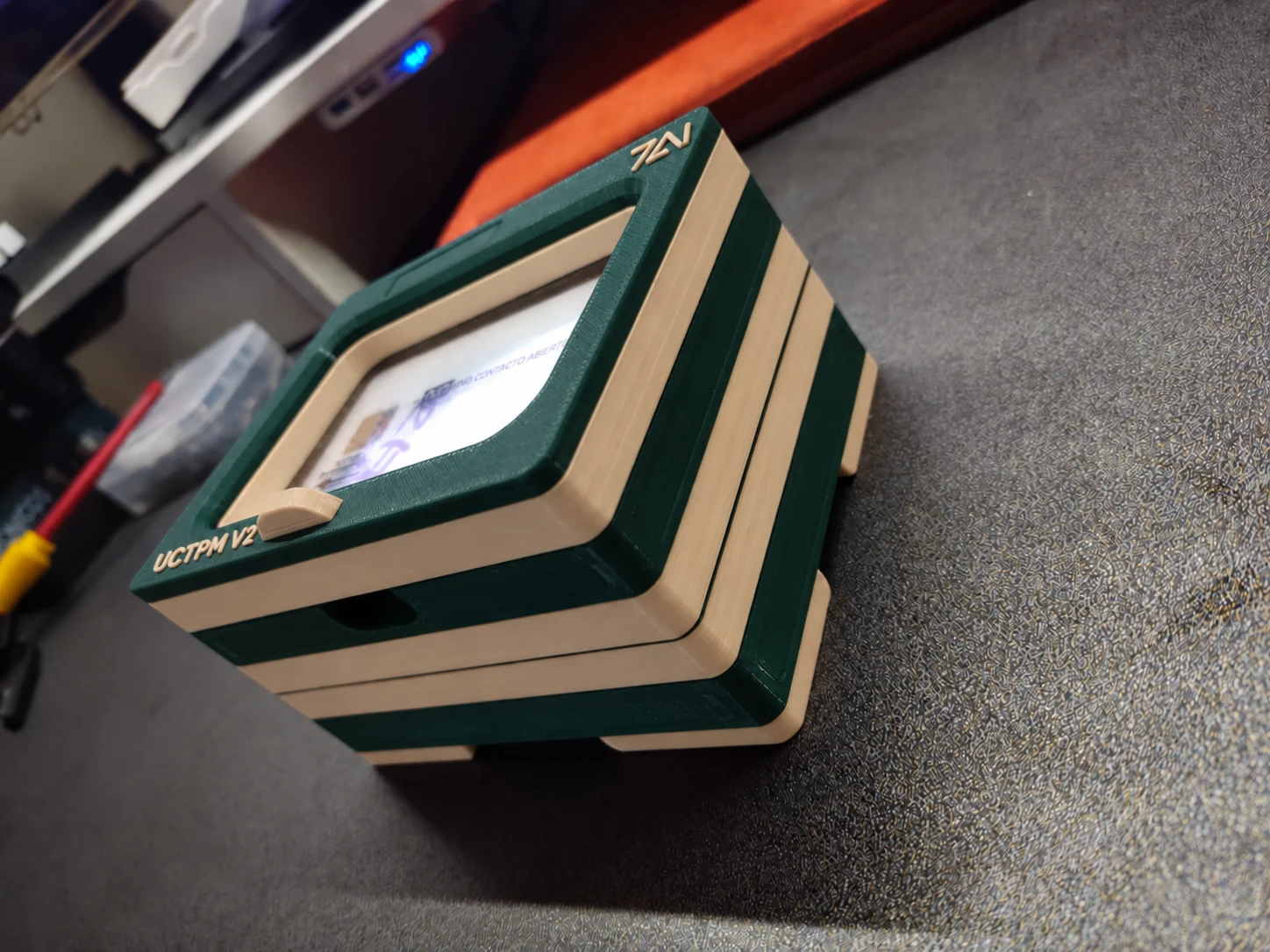
In the milling department, the same reference could remain in production for several days. The multiple fixture was configured at the start of the run and remained ready for that job.
With the corresponding template on top, successive checks consist of placing the card, closing the lid and comparing the milled cavity with the reference.
03 / HOW IT ASSEMBLES
The animation shows the base, templates, nest and lid that make up the assembly. Screws secure the assembly once the nest is seated.
Opening the lid with its template installed leaves the card recess clear. The nest positions the part and the template provides the reference for checking the milled cavity.
Assembly and opening play automatically. You can pause the video at any time.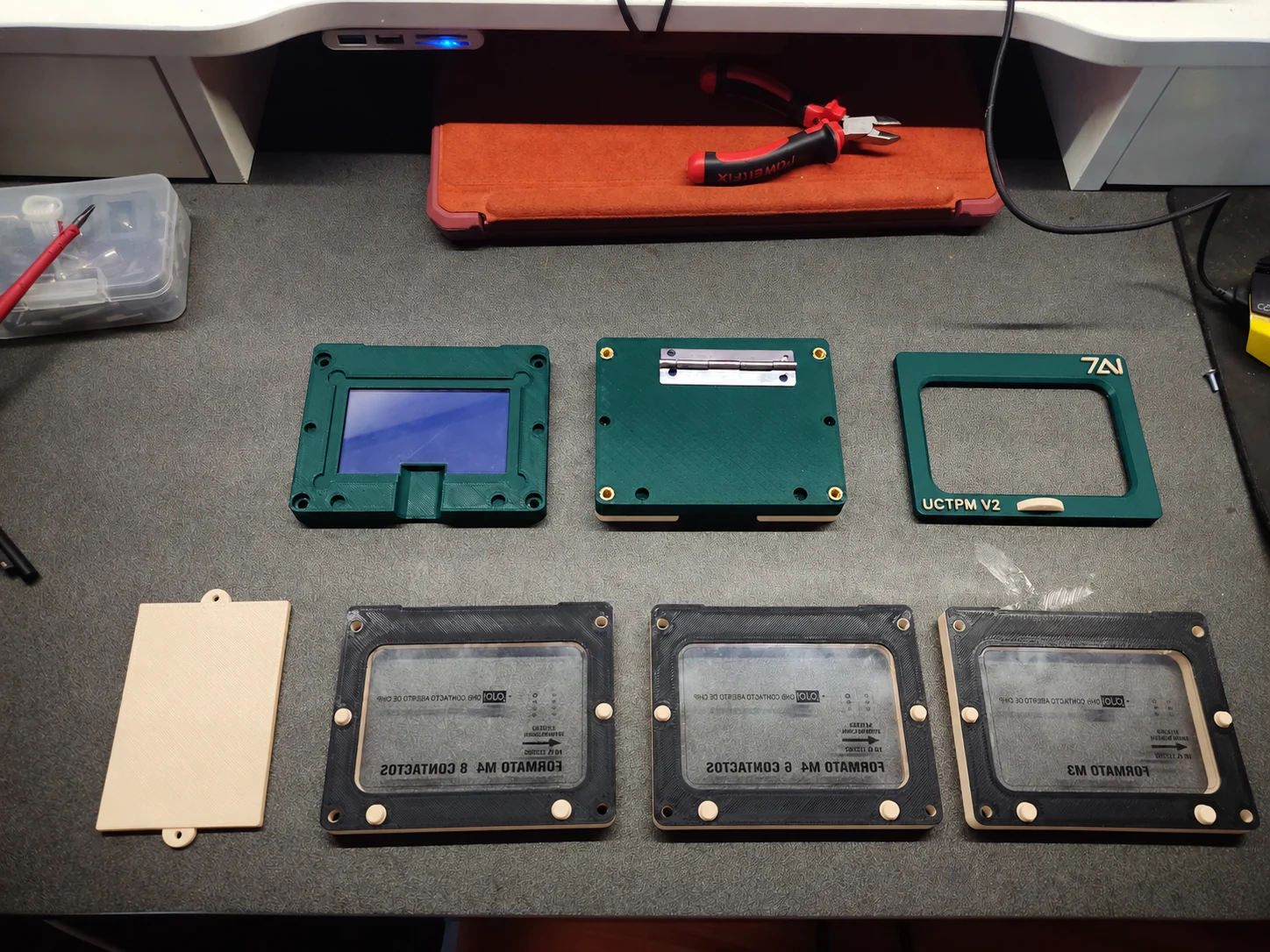
04 / TEMPLATES AND VERIFICATION
The exploded view shows the templates and components of the multiple fixture. Each template corresponds to a specific milling configuration.
The base incorporates a compartment for three reference cards, one per template. They allow periodic checks that the template remains aligned before work continues.
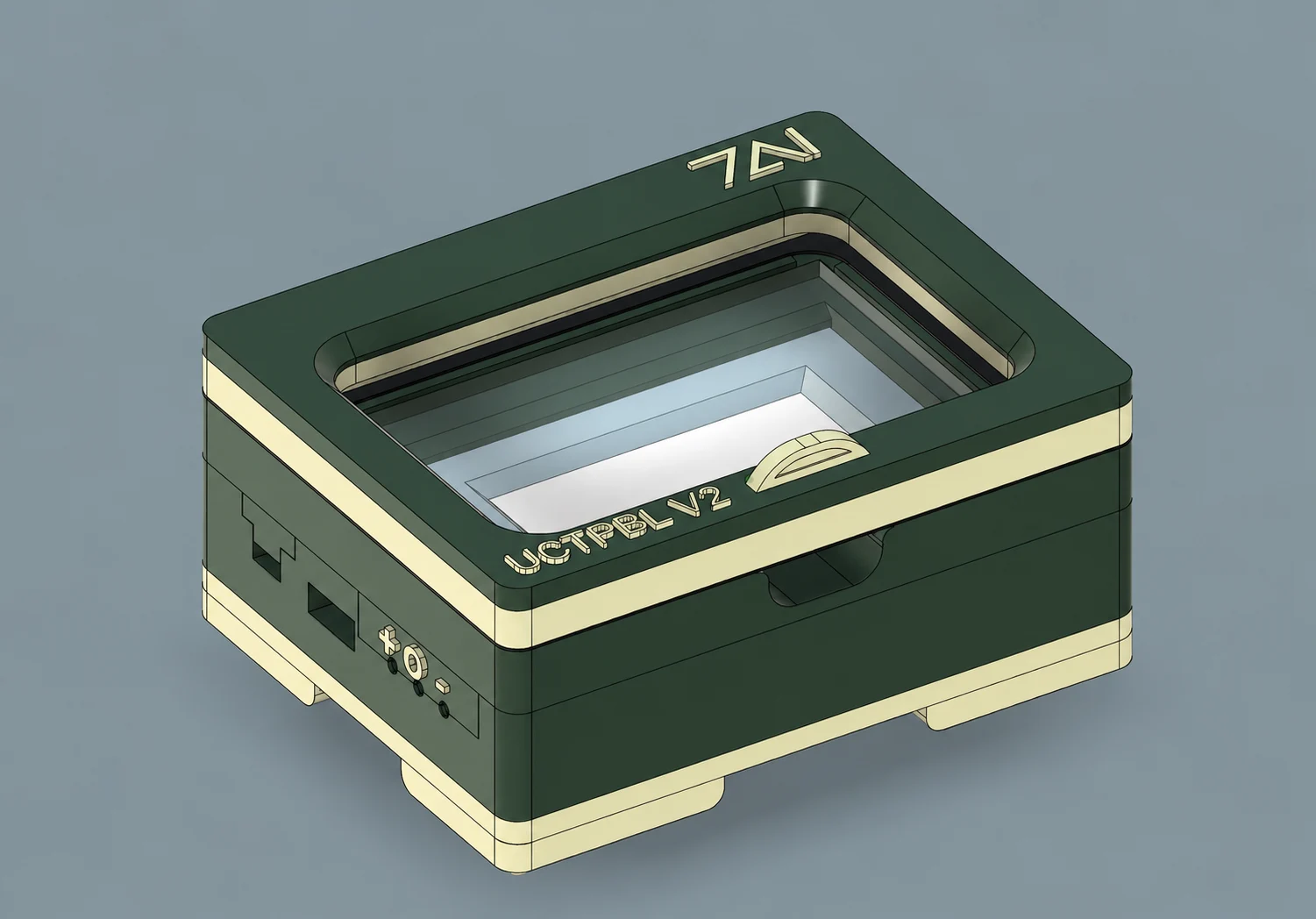
UCTPBL V2
03 / UCTPBL V2
During ticket manufacture, the chip and antenna are hidden between two layers of paper. When setting up the machine, the outside appearance alone was insufficient to determine whether that internal assembly was correctly positioned.
The Backlight fixture was developed to reveal the inside of an individual sample. A displacement could leave the antenna exposed to a later cut without being visible to the naked eye. Light allows its position to be checked; electronic testing is a separate check.
01 / THE DESIGN
The body combines lower lighting, the positioning nest and a hinged lid with inspection references. A self-contained assembly for checking individual tickets during machine setup and production checks.
02 / POSITION THE TICKET
The ticket is placed in the fixed nest. Lowering the lid aligns the template through its guide points and holds the assembly in place, avoiding the need to slide an overlay by hand to match the edges.
Preparing view…
03 / THE TEMPLATE
The lid carries the marks for the product: antenna and chip positions, printing, logos and other references. The template allows these features to be compared with their intended positions in a single check.
04 / OPEN AND CHECK
After die-cutting, units are checked one at a time. The open lid leaves the nest clear to remove the sample and insert the next one, maintaining the same reference recess throughout inspection.
05 / LIGHTING AND BATTERY LIFE
The power button activates the COB lighting; the + and − controls select between four intensity levels. An LED bar indicates battery status and charging is via USB.
The battery of around 3,000 mAh provides approximately four hours of operation, depending on use. Lighting is activated by the controls, independently of the lid position.
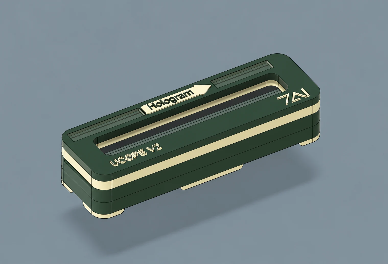
UCCPE V2
04 / UCCPE V2
Continuous ticket stock passes through the fixture to check sections of the reel. The template compares the position and angle of the stripe and hologram against their permitted limits.
Used during stripe and hologram application, it helps detect deviations and readjust the machine.
01 / THE DESIGN
The longitudinal passage allows the strip to be inserted and moved through the fixture to check different sections of the reel. The template places inspection references over the stripe and hologram.
The “Hologram” arrow indicates the hologram's direction of travel and immediately guides strip placement. A visual guide that reduces uncertainty in use and reinforces the fixture's poka-yoke approach.
02 / IN PRODUCTION
The fixture was distributed among stripe and hologram application stations. Later, a material issue led to additional units being manufactured so that the recipient could inspect incoming material.
The inspection reference therefore extended from manufacture to reception: both parties could check the strip using the same criteria. Years later, another batch of fixtures was ordered.
UCTPSI V2
05 / UCTPSI V2
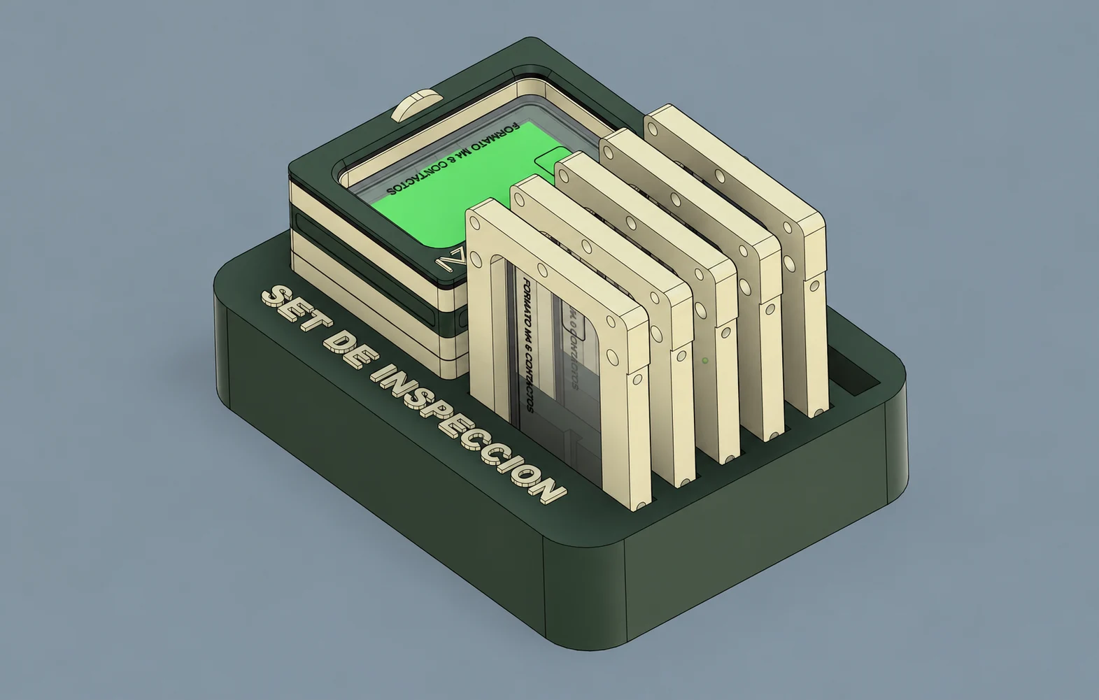
As the system spread through the factory, the number of templates for different products increased too. The inspection department needed to bring them together and have them available at a single station.
The set addressed that need: a fixture with interchangeable templates and a storage recess. Each reference includes its own checks for chip position, printing or other features. Inspection remains manual, card by card.
THE SET IN MOTION
Changing the five stored templates with the installed one until the first is restored. After each change, the lid pivots with its template and closes again before the next change. Animation of the 3D model.
03 / A PATH THAT CONTINUES
Phone holder for repeatable framing and a reader base to add electronic checks. Planned developments, not yet manufactured.
Automatic card feeding, transport and turnover. Vision inspection remains in validation.
A modular machine with interchangeable beds and planned extensions for inspecting strips and complete reels.
04 / SYSTEM EVOLUTION
Select a stage with variants to explore its configurations ↓
 02
From fixture to evidence
Available for the familyView NFC and platform ↑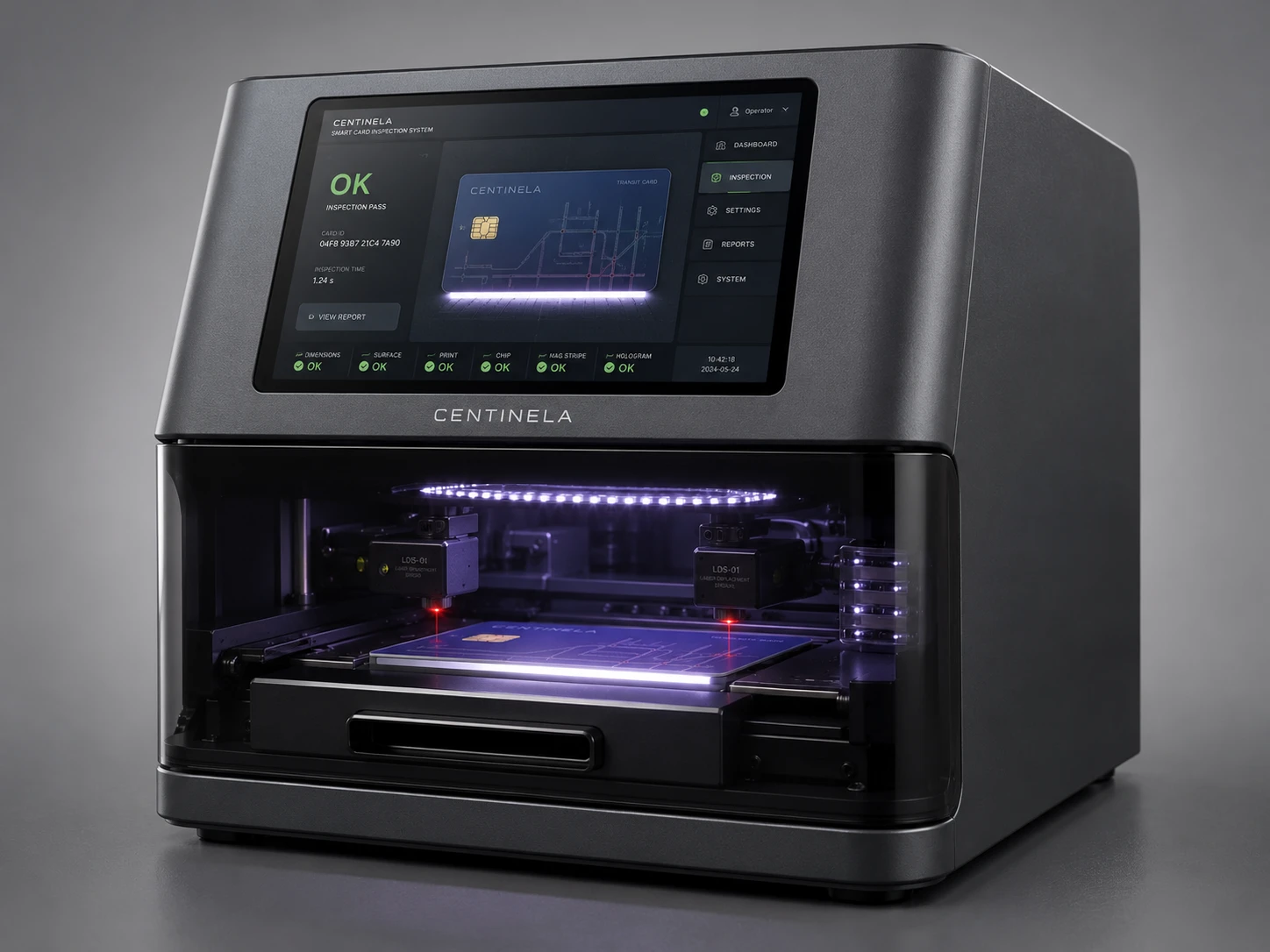 06
The next evolution
Design render01 / Family in use
One tool for each check. Explore the five models in the family.
A fixed reference, ready for checks at each station.
View fixture →Three configurations in one fixture.
View fixture →Backlighting to observe the internal inlay.
View fixture →Stripe and hologram checks on continuous stock.
View fixture →Templates organised for different references.
View fixture →03 / Design variants
ChipCheck 1 was conceived as a compact machine to automate card inspection: checking the internal chip and, in the camera-equipped version, visually inspecting one side. The aim was to move a task repeated card by card at the inspection station onto a machine.
The designs show how card collection could be adapted: a single output, two stackers to alternate collection and increase capacity, or a rotary sorter to separate cards according to the detected defect. These are design variants of the compact machine; the requirement to inspect both sides led to ChipCheck V2.
Initial configuration for checking the chip.
Incorporates visual inspection on one side.
Mobile assembly with stacker storage.
Two outputs to alternate collection and increase capacity.
Rotary output design for sorting according to the detected defect.
04 / Built · vision under test
ChipCheck V2 is designed to inspect both sides of cards automatically and separate accepted cards from rejected ones. Cards are loaded into a stacker; the system feeds them, transports them through the inspection stations and flips them so the front and back can be examined.
The need to incorporate four cameras and the flipping mechanism led to a redesign of the compact equipment and the development of a larger machine. The photograph shows the built machine: feeding, transport and card flipping are operational; machine vision inspection, provided through an external integration, remains under validation.
Photograph of the manufactured machine, with card feeding, transport and turnover. Vision inspection remains in validation.
05 / Modular design
Centinela is designed to adapt one inspection machine to different products: RFID prelam, individual cards, ticket-web samples and complete reels. It combines backlighting and a camera for AI-based vision inspection, with interchangeable beds that position each format in the inspection area.
The idea is to expand the machine in stages according to the work required. For complete reels, the configuration includes unwinding and rewinding: the web passes through the inspection area to be checked from beginning to end. The four configurations shown are design developments that have not yet been manufactured.
Bed for inspecting RFID prelam antennas and checking their condition and position using backlighting and vision.
Positioning base for inspecting cards one at a time.
Bed for checking strip sections with the lighting and camera system.
Automated configuration with unwinding and rewinding, designed to inspect the entire strip from start to finish.
Your next step
We can study an inspection fixture tailored to your part, workstation and process criteria.